
Drilling device for metal pipe machining

A drilling device and metal pipe technology, which is applied in metal processing equipment, metal processing mechanical parts, positioning devices, etc., can solve the problems of inaccurate position, product scrapping production efficiency, high labor intensity of staff, etc., and achieve processing positioning. and alignment, improve work efficiency

Pending Publication Date: 2018-04-13
无锡市汇鼎金属制管有限公司
View PDF18 Cites 0 Cited by
  • Summary
  • Abstract
  • Description
  • Claims
  • Application Information

AI Technical Summary

Problems solved by technology

[0002] Metal pipe is an indispensable material in petroleum, chemical, medical, food, light industry, mechanical instrumentation and other industries and all walks of life, including iron pipe, steel pipe, stainless steel pipe and aluminum pipe, etc. , so various processing equipment for metal pipes have emerged as the times require. Among them, drilling metal pipes is a common processing method. Drilling refers to the operation of machining holes on solid materials with drill bits. The current drilling The hole equipment is affected by human manual operation factors, which may easily cause the position of the hole to be inaccurate, make mistakes during the drilling operation, lead to product scrapping and low production efficiency, and the labor intensity of the staff is high

Method used


Image

  • Drilling device for metal pipe machining
  • Drilling device for metal pipe machining
  • Drilling device for metal pipe machining

Examples


Embodiment Construction

[0019] The present invention will be further described below in conjunction with accompanying drawing:

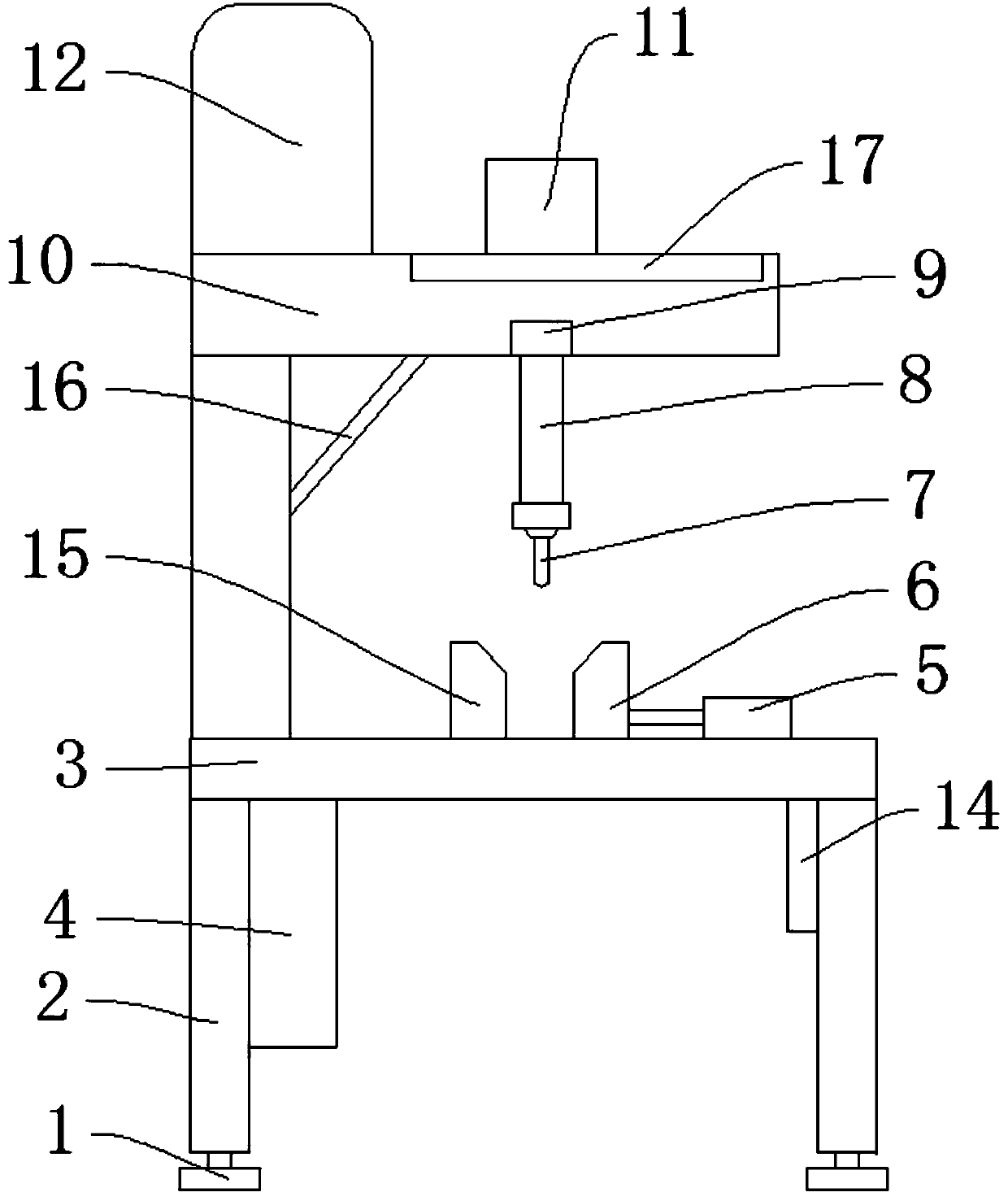
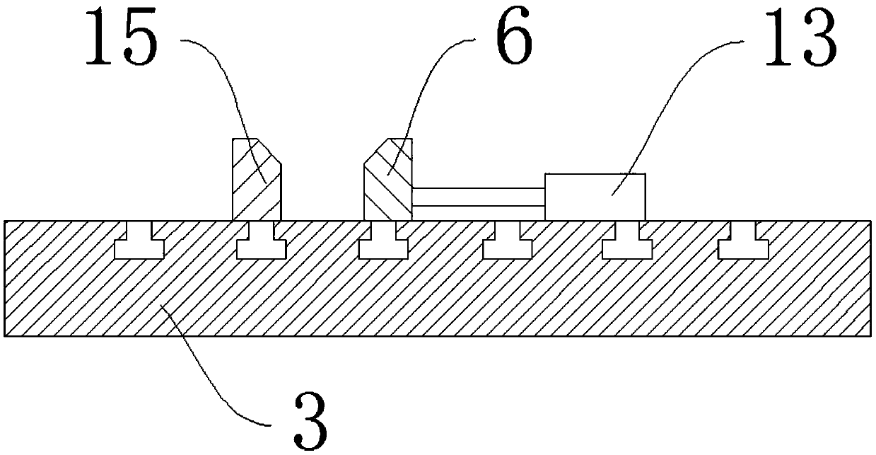
[0020] Such as Figure 1-Figure 3 As shown, a drilling device for metal pipe processing includes a base plate 3, a motor 12, a control box 4, and a clamping device 18. A support 2 is arranged under the base plate 3, and an adjustable base 31 is provided at the lower end of the support 2. The bottom of the base plate 3 is close to the support. The operation panel 14 is set at 2 places, and the control box 4 is set at the bottom of the bottom plate 3 away from the operation panel 14. The clamping device 18 includes the first V-shaped block 6, the second V-shaped block 15, the first electric push rod 5, the second electric push rod Rod 13, the first electric push rod 5 is set on one side of the first V-shaped block 6, the second electric push rod 13 is set on the first V-shaped block 6 away from the first electric push rod 5, and the bottom plate 3 is close to the first V-shap...


PUM


Abstract

The invention discloses a drilling device for metal pipe machining. The drilling device comprises a bottom plate, a motor, a control cabinet and a clamping device. A support is arranged below the bottom plate, an adjustable base is arranged at the lower end of the support, an operation panel is arranged at the position, close to the support, below the bottom plate, and the control cabinet is arranged at the position, away from the operation panel, below the bottom plate. The clamping device comprises a first V-shaped block, a second V-shaped block, a first electric push rod and a second electric push rod. The first V-shaped block is arranged above the bottom plate, the first electric push rod is arranged on one side of the first V-shaped block, a second electric push rod is arranged at theposition, away from the first electric push rod, of the first V-shaped block, and the second V-shaped block is arranged at the position, close to the first V-shaped block, above the bottom plate. Thedrilling device has the beneficial effects that a metal pipe is rapidly positioned by the clamping device, the accuracy of the drilling position is judged by using an infrared emitter, machining positioning and aligning can be rapidly achieved, and the working efficiency is improved.

Description

technical field [0001] The invention relates to the technical field of metal pipe processing equipment, in particular to a drilling device for metal pipe processing. Background technique [0002] Metal pipe is an indispensable material in petroleum, chemical, medical, food, light industry, mechanical instrumentation and other industries and all walks of life, including iron pipe, steel pipe, stainless steel pipe and aluminum pipe, etc. , so various processing equipment for metal pipes have emerged as the times require. Among them, drilling metal pipes is a common processing method. Drilling refers to the operation of machining holes on solid materials with drill bits. The current drilling Drilling equipment is affected by human manual operation factors, which can easily cause inaccurate positions after drilling, and mistakes are prone to occur during drilling operations, resulting in product scrapping and low production efficiency, and the labor intensity of the staff is hig...

Claims


Application Information

Patent Timeline
Patent Type & Authority Applications(China)
IPC IPC(8): B23B41/00B23Q3/06B23Q17/24B23Q17/22
CPCB23B41/00B23Q3/064B23Q17/2428
Inventor 陈海兵
Owner 无锡市汇鼎金属制管有限公司
Learn More