
Spiral groove machining device for automobile sleeve

A sleeve spiral and groove processing technology, applied in metal processing equipment, metal processing mechanical parts, turning equipment, etc., can solve the problems of complex operation procedures, long production time, low production efficiency, etc., to reduce the number of procedures and achieve good cutting effect. , the effect of improving processing efficiency

Pending Publication Date: 2018-04-13
重庆朗奥机械有限公司
View PDF10 Cites 5 Cited by
  • Summary
  • Abstract
  • Description
  • Claims
  • Application Information

AI Technical Summary

Problems solved by technology

[0003] Aiming at the deficiencies in the prior art, the present invention provides a spiral groove processing device for automobile sleeves, which solves the problem of long production time, complicated operation procedures and production problems caused by the processing of automobile sleeves in the prior art using existing machine tools. The problem of inefficiency

Method used


Image

  • Spiral groove machining device for automobile sleeve
  • Spiral groove machining device for automobile sleeve
  • Spiral groove machining device for automobile sleeve

Examples


Embodiment Construction

[0019] The present invention will be further described below in conjunction with the accompanying drawings.

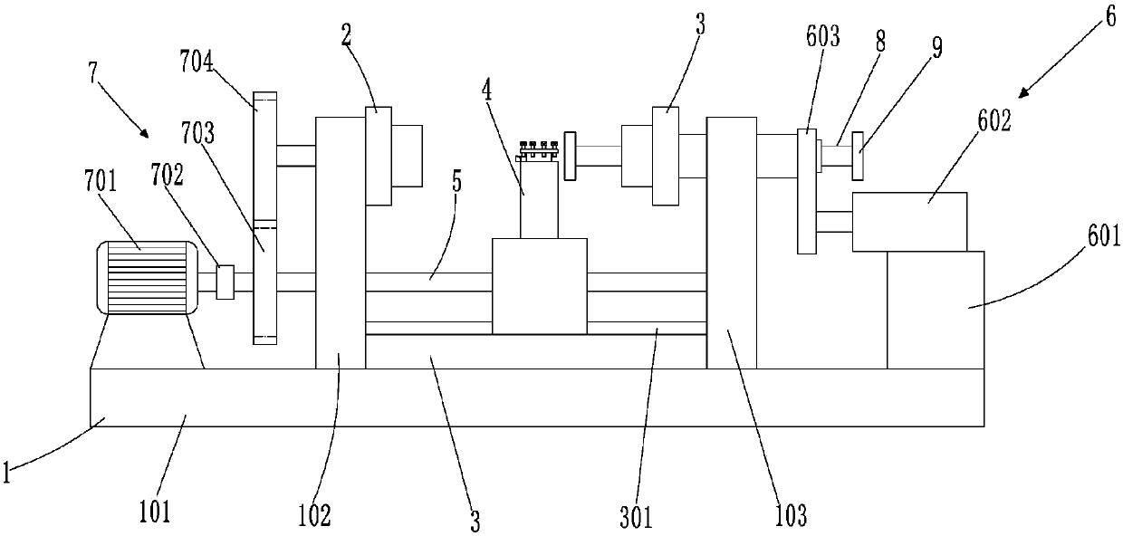
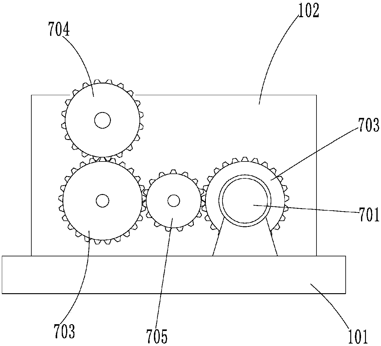
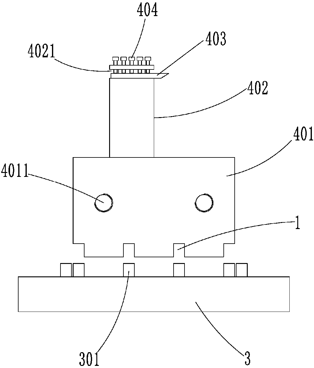
[0020] Such as Figure 1 to Figure 6 As shown, a kind of automotive sleeve spiral groove processing device according to the present invention includes a machine base 1, and the machine base 1 includes a base plate 101 and a first support plate 102 and a second support plate 103 fixed on the base plate 101 at intervals, The first support plate 102 is rotated with a positioning shaft 2, and the second support plate 103 is slidably provided with a pressing shaft 3 concentric with the positioning shaft 2, and the position where the pressing shaft 3 extends out of the second support plate 103 is connected with a The hydraulic drive device 6, because the whole device is specially used for processing the spiral groove of the sleeve, the length of the sleeve is fixed, so the positions of the first support plate 102 and the second support plate 103 are fixed. The positioning s...


PUM


Abstract

The invention provides a spiral groove machining device for an automobile sleeve. The spiral groove machining device comprises a machine base; the machine base includes a bottom plate, a first supporting plate and a second supporting plate, wherein the first supporting plate and the second supporting plate are fixedly connected on the bottom plate at intervals, the first supporting plate is provided with a positioning shaft in a rotating mode, the second supporting plate is provided with a pressing shaft concentric with the positioning shaft in a sliding mode, and a hydraulic driving device isconnected with the portion, extending out the second supporting plate, of the pressing shaft; the bottom plate between the first supporting plate and the second supporting plate is fixedly connectedwith a sliding seat, and a tool holder assembly is arranged on the sliding seat in a sliding mode; two parallel screw rods are arranged between the first supporting plate and the second supporting plate, and the screw rods are connected with the tool holder assembly in a spiral motion mode; and a driving mechanism for driving the positioning shaft and the screw rods to rotate synchronously is disposed at the outside of the first supporting plate. According to the spiral groove machining device for the automobile sleeve, a spiral groove in a sleeve blank is machined by the special machining device to avoid occupying the normal use of a standard machine tool, the machining efficiency is improved, procedures in the machining process are reduced, the size is consistent during each time of machining, and the replaceability is achieved.

Description

technical field [0001] The invention relates to the technical field of machining, in particular to an automobile sleeve spiral groove processing device. Background technique [0002] For special-purpose auto parts, they are verified by standard machine tools before formal production. After formal production, they need to be mass-produced to reduce production costs and improve production efficiency. The sleeves used in automobiles are processed with spiral grooves on the outer surface for supporting use. Due to the particularity of the processing method, batch processing with standard machine tools will cause waste of resources, and the machine tool must be debugged before each processing, and tooling must be added for positioning. , so that the production time becomes longer, the operation process is complicated, and the production efficiency is reduced. Contents of the invention [0003] Aiming at the deficiencies in the prior art, the present invention provides a spiral...

Claims


Application Information

Patent Timeline
Patent Type & Authority Applications(China)
IPC IPC(8): B23B5/48B23B21/00
CPCB23B5/48B23Q1/25
Inventor 陈东陈庆陈荣
Owner 重庆朗奥机械有限公司
Learn More