
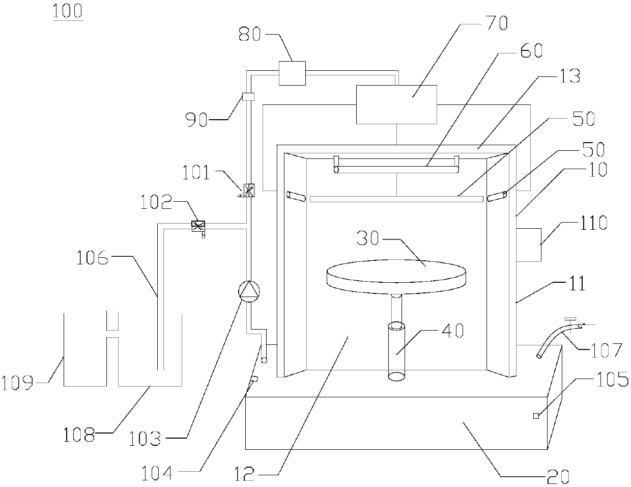
Paint spraying room with water circulation system

A paint spraying and water circulation technology, applied in spray booths, spraying devices, etc., can solve the problems of uneven water flow speed, environmental pollution, influence of paint waste gas absorption effect, etc., to improve waste gas treatment efficiency, uniform water flow speed, and avoid transmission difficulties. Effect

Pending Publication Date: 2018-04-13
湖北三叶机电制造股份有限公司
View PDF6 Cites 2 Cited by
  • Summary
  • Abstract
  • Description
  • Claims
  • Application Information

AI Technical Summary

Problems solved by technology

Because the water pump in the existing water circulation system used in the paint spraying room is directly connected to the water spray pipe, and it is transmitted from a low place to a high place, resulting in uneven water flow velocity from the water spray pipe, so the waste gas treatment efficiency is not high, and the free gas is Part of the paint mist in the air will be absorbed by the water curtain produced by the water curtain machine, but there is still a considerable part of the paint mist that cannot be absorbed and discharged into the atmosphere from the sewage pipe, causing serious environmental pollution
In addition, the existing water circulation system used in the paint spray room cannot actively adjust the temperature of the sprayed circulating water, which has a bad influence on the absorption effect of paint exhaust gas

Method used


Image

  • Paint spraying room with water circulation system

Examples


Embodiment Construction

[0027] The following is attached figure 1 The principles and features of the present invention are described, and the examples given are only used to explain the present invention, and are not used to limit the scope of the present invention. In the following paragraphs the invention is described more specifically by way of example with reference to the accompanying drawings. Advantages and features of the present invention will be apparent from the following description and claims. It should be noted that all the drawings are in a very simplified form and use imprecise scales, and are only used to facilitate and clearly assist the purpose of illustrating the embodiments of the present invention.

[0028] It should be noted that when a component is said to be "fixed" to another component, it can be directly on the other component or there can also be an intervening component. When a component is said to be "connected" to another component, it may be directly connected to the...


PUM


Abstract

The invention relates to a paint spraying room with a water circulation system. The paint spraying room comprises a paint spraying room body, an auxiliary water tank, a heat exchanger, a water pump and a controller, wherein a circulation water pool is arranged below the paint spraying room body; the paint spraying room body comprises two sidewalls and a rear wall; the two sidewalls are arranged atthe two sides of the rear wall; a water spray pipe is arranged on the two sidewalls and the rear wall separately; each water spray pipe communicates with the auxiliary water tank; the auxiliary watertank sequentially communicates with the heat exchanger and the water pump; the auxiliary water tank is located above the paint spraying room body; the water pump communicates with the circulation water pool; a temperature sensor is arranged in the circulation water pool; and the controller is electrically connected with the heat exchanger and the temperature sensor separately. According to the paint spraying room disclosed by the invention, one water spray pipe is arranged on the upper parts of the two sidewalls and the rear wall separately, and the waste gas of a paint is absorbed from threedirections, so that treatment efficiency for the waste gas is greatly increased; and a uniform speed of water flow sprayed by the water spray pipes is ensured by virtue of a gravity factor, so that the treatment efficiency for the waste gas is increased, and circulation water is stored in advance, so that difficult transmission for the circulation water from a low place to a high place is avoided.

Description

technical field [0001] The invention relates to the field of paint waste gas treatment, in particular to a paint spray booth with a water circulation system. Background technique [0002] After many industrial products (such as auto parts and various optical cable equipment) are finished, the surface must be polished, sprayed with paint, and dried to form a finished product. The paint spray booth is used to spray paint for these industrial products. In addition to spraying on the workpiece, about 20% of the paint mist that is atomized during the paint spraying process will not be able to adhere, but will be free in the air. [0003] In the existing paint room, there is usually a main body of the paint room, on which facilities such as a pressure-tight door, a supplementary fan, a water curtain machine, and a circulating pool are provided, and a sewage pipe directly connected with the outside is provided. Because the water pump in the existing water circulation system used i...

Claims


Application Information

Patent Timeline
IPC IPC(8): B05B16/40B05B14/465B05B13/02
CPCB05B13/0221
Inventor 毛砚锋毛叶鹏
Owner 湖北三叶机电制造股份有限公司
Learn More