
Double dielectric barrier discharge device used for foul exhaust gas treatment

A technology for blocking discharge and waste gas treatment, which is applied to the separation of dispersed particles, chemical instruments and methods, and separation methods. It can solve the problems of inconvenient disassembly and achieve the effects of good sealing, convenient disassembly, and high efficiency of waste gas treatment.

Pending Publication Date: 2019-08-16
QINGDAO DOUBLESTAR ENVIRONMENTAL PROTECTION EQUIP
View PDF1 Cites 2 Cited by
  • Summary
  • Abstract
  • Description
  • Claims
  • Application Information

AI Technical Summary

Problems solved by technology

[0005] Aiming at the deficiencies of the existing technology, the technical problem to be solved by the present invention is to overcome the inconvenient disassembly of the existing row-type double dielectric barrier discharge device when it is used for the treatment of malodorous gas, which is caused by improper sealing and insulation treatment. In order to solve the problem of potential safety hazards, a dual-dielectric barrier discharge device for malodorous exhaust gas treatment is proposed, which is easy to disassemble, has good sealing and insulation properties, and has high safety

Method used


Image

  • Double dielectric barrier discharge device used for foul exhaust gas treatment
  • Double dielectric barrier discharge device used for foul exhaust gas treatment
  • Double dielectric barrier discharge device used for foul exhaust gas treatment

Examples


Embodiment Construction

[0027] In the following, the present invention will be specifically described through exemplary embodiments. It should be understood, however, that elements, structures and characteristics of one embodiment may be beneficially incorporated in other embodiments without further recitation.

[0028] In the description of the present invention, it should be understood that the terms "first" and "second" are used for description purposes only, and cannot be interpreted as indicating or implying relative importance or implicitly indicating the quantity of indicated technical features. Thus, a feature defined as "first" and "second" may explicitly or implicitly include one or more of these features.

[0029] In the description of the present invention, it should be understood that the orientation or positional relationship indicated by the terms "upper", "lower", "bottom", "inner" and "outer" are based on the attached figure 1 The orientations or positional relationships shown are o...


PUM


Abstract

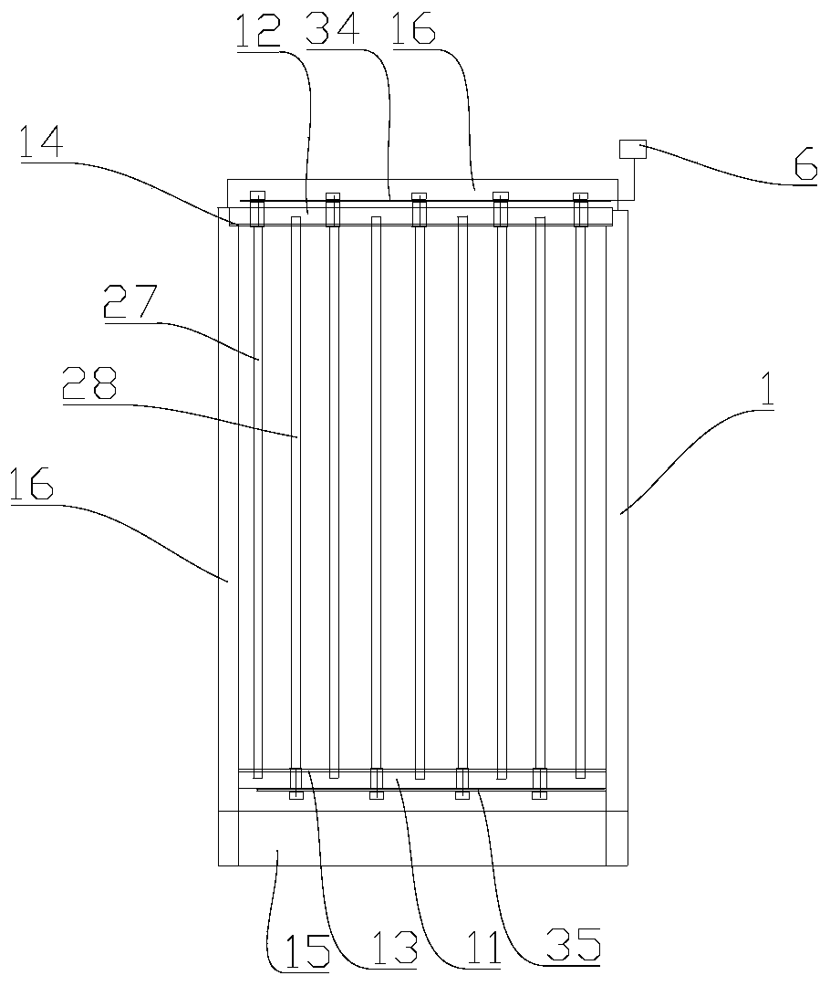
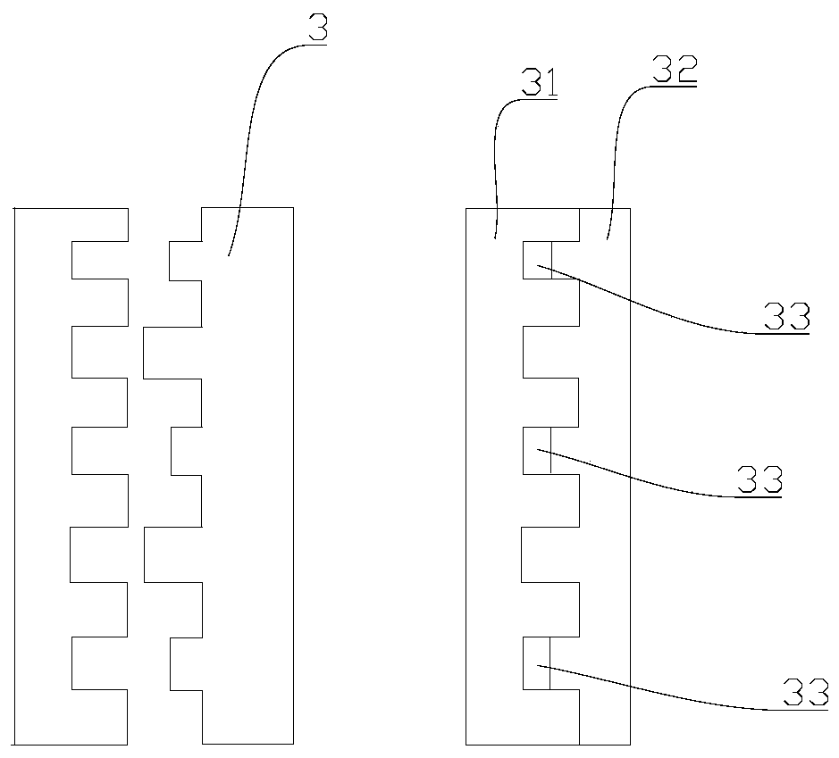
The invention discloses a double dielectric barrier discharge device used for foul exhaust gas treatment, and belongs to the field of foul pollutant treatment equipment. The double dielectric barrierdischarge device used for foul exhaust gas treatment comprises a frame and at least two battery lead plates, wherein the battery lead plates are installed on the frame, an installation base is arranged at the lower end of the frame, an installation board which is arranged opposite to the installation base is arranged at the upper end of the frame, first installation blind holes and first installation through holes are formed in the installation base alternatively, second installation blind holes and second installation through holes are formed in the installation board alternatively, the firstinstallation blind holes are formed opposite to the second installation through holes, and the first installation through holes are formed opposite to the second installation blind holes. The doubledielectric barrier discharge device used for foul exhaust gas treatment is applied for the aspect of foul exhaust gas treatment, the problems that when an existing exclusive-stage double dielectric barrier discharge device is used for foul exhaust gas treatment, detachment is inconvenient, and potential safety hazards are caused due to improper sealing and insulation treatment are solved, and thedouble dielectric barrier discharge device used for foul exhaust gas treatment has the characters that detachment is convenient, the sealing property and the insulativity are good, and the safety is high.

Description

technical field [0001] The invention belongs to the field of malodorous pollutant treatment equipment, in particular to a double-dielectric barrier discharge device for malodorous waste gas treatment. Background technique [0002] As a reliable and economical method to generate low-temperature (non-equilibrium) plasma under normal pressure, double dielectric barrier discharge (DDBD) is widely used in the fields of ozone synthesis, vacuum ultraviolet light source, material surface treatment and environmental protection. In recent years, research on the degradation of odorous pollutants by DDBD technology has attracted much attention, and because of its characteristics of large-space uniform discharge of glow discharge and high-pressure operation of corona discharge, it has become an odorous pollutant with industrial application prospects. Effective technologies for pollution control. At present, the plasma generation methods of double dielectric barrier discharge mainly incl...

Claims


Application Information

Patent Timeline
IPC IPC(8): B01D53/32
CPCB01D53/32
Inventor 徐楠楠柴方刚韩月丽周志伟刘培华
Owner QINGDAO DOUBLESTAR ENVIRONMENTAL PROTECTION EQUIP
Learn More