
Thinner and lighter display device

A display device, thinning technology, applied in nonlinear optics, instruments, optics, etc., can solve the problems of large thickness of the display device, not conforming to the development trend of thin and light TVs, and overheating of the light source.

Active Publication Date: 2018-04-10
HUIZHOU CHINA STAR OPTOELECTRONICS TECHNOLOGY CO LTD
View PDF5 Cites 1 Cited by
  • Summary
  • Abstract
  • Description
  • Claims
  • Application Information

AI Technical Summary

Problems solved by technology

However, the above surface area is often limited by the size of the display panel of the backlight module, which affects its heat dissipation efficiency, so that the backlight module will overheat its light source due to poor heat dissipation, which will shorten the service life of the backlight module and reduce its luminous efficiency.
In order to improve the heat dissipation efficiency, some manufacturers also make a large number of heat dissipation fins on the back of the display backplane to dissipate heat. By increasing the heat dissipation fins, the heat dissipation efficiency is obviously improved. However, this also directly leads to a larger thickness of the display device. , and the overall appearance is very bulky, which does not conform to the current development trend of thin and light TV sets

Method used


Image

  • Thinner and lighter display device
  • Thinner and lighter display device
  • Thinner and lighter display device

Examples


Embodiment Construction

[0028] In order to make the object, technical solution and advantages of the present invention more clear, the present invention will be further described in detail below in conjunction with the accompanying drawings and embodiments. It should be understood that the specific embodiments described here are only used to explain the present invention, not to limit the present invention.

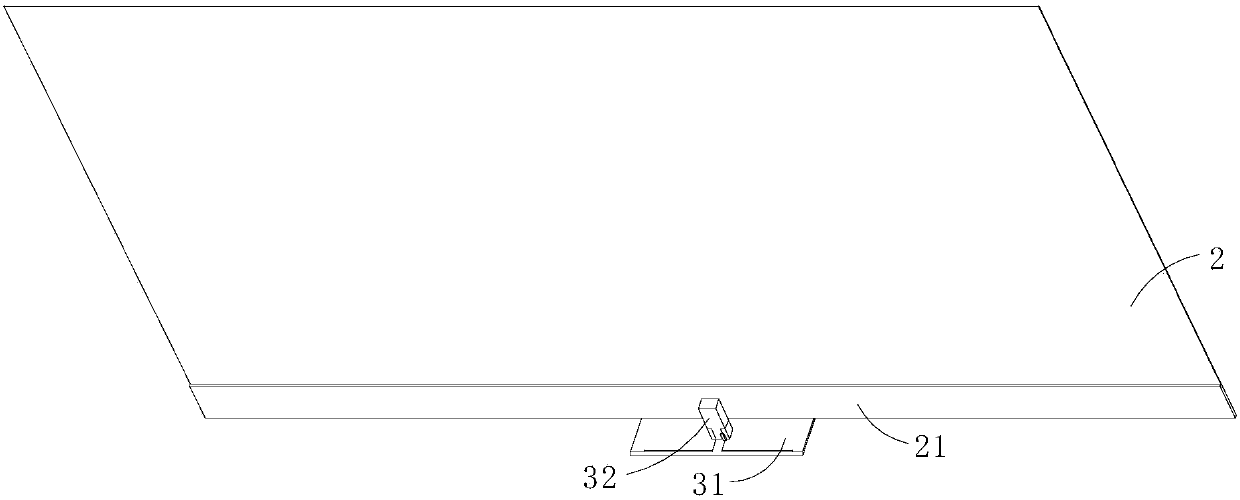
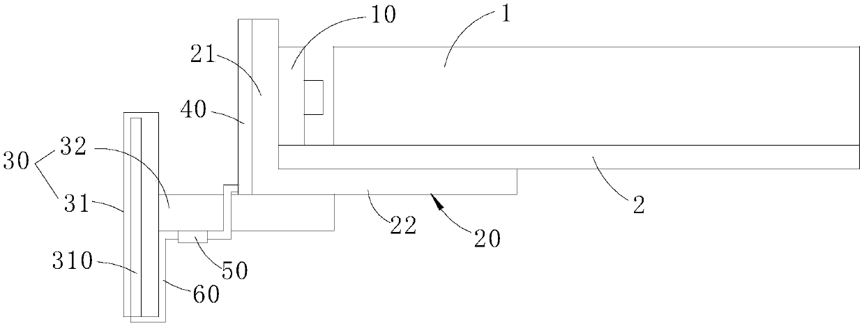
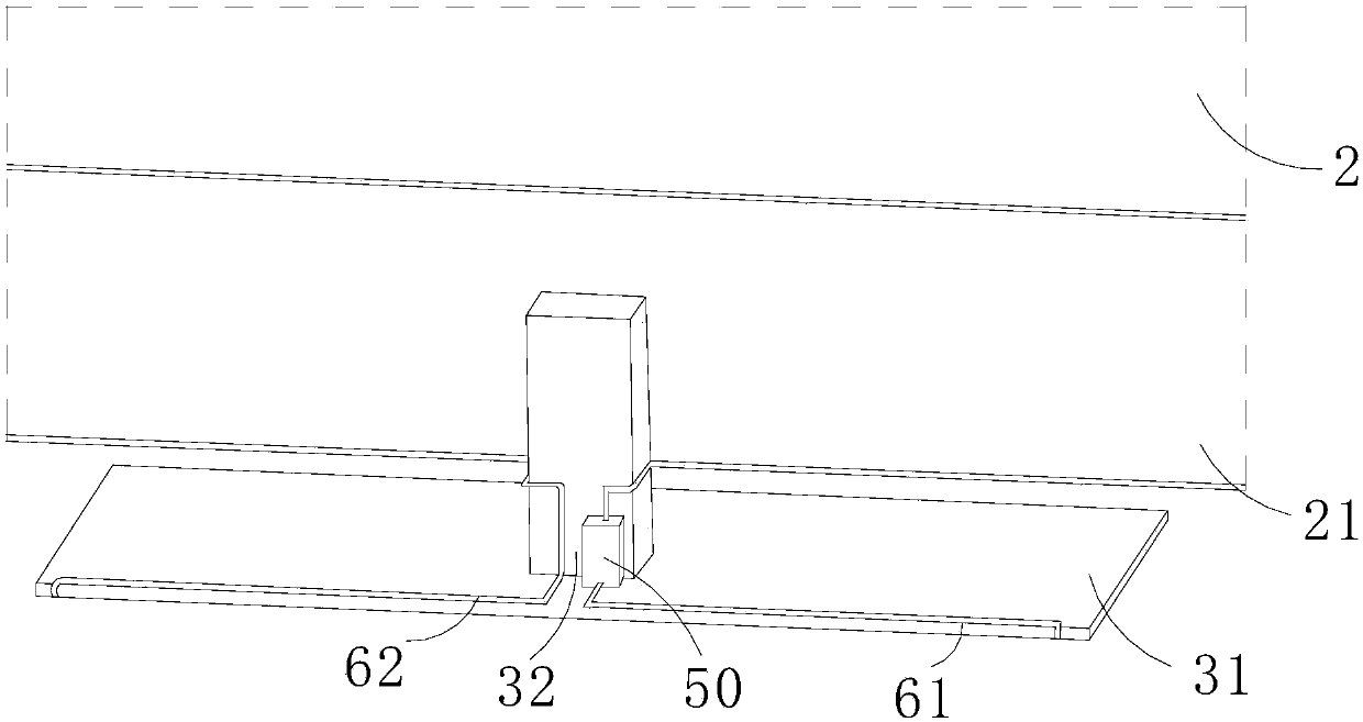
[0029] refer to figure 1 and figure 2 , the display device of the embodiment of the present invention mainly includes a light guide plate 1, an LED light bar 10, a heat dissipation plate 20, a base 30 and a water cooling tube 40, and the LED light bar 10 is arranged at the light incident end of the light guide plate 1, and the LED light bar 10 emits After the light enters the light guide plate 1 from the side, it is uniformly treated by the light guide plate 1 and emitted from its top surface as a backlight source. side. It can be understood that the display device also includes a display pa...


PUM


Abstract

The invention discloses a thinner and lighter display device. The thinner and lighter display device comprises a light guiding plate, an LED light bar, a heat dissipating plate, a base and a water cooling tube, wherein the light guiding plate is used for conducting light rays; the LED light bar is arranged at a light incident end of the light guiding plate and is used for emitting light rays toward the light guiding plate; the heat dissipating plate is arranged beside the LED light bar, and the LED light bar fits to the inner side of the heat dissipating plate; the base is connected with the outer side of the heat dissipating plate and used for supporting the display device; and the water cooling tube comprises an inlet end, an outlet end and multiple buckling sections which are connectedbetween the inlet end and the outlet end, the buckling sections fit to the heat dissipating plate and are used for enabling a cooling liquid to be circulated, and the cooling liquid enters from the inlet end and then flows out from the outlet end and takes away heat on the heat dissipating plate. The invention provides a new heat dissipation structure of the display device, area of the heat dissipating plate is reduced and use of a heat dissipating fin is avoided by fully utilizing heat dissipating capabilities of the heat dissipating plate and a heat conducting base, so that the display device has good heat dissipation effect while guaranteeing that the display device is thinner and lighter, and cost of a heat dissipation structure is reduced.

Description

technical field [0001] The present invention relates to the field of display technology, in particular to a light and thin display device. Background technique [0002] Since the liquid crystal itself does not emit light, the backlight module is a key component of the Liquid Crystal Display (LCD) panel. Its main function is to supply a light source with sufficient brightness and uniform distribution so that the LCD panel can display images normally. As LCD panels have been widely used in many electronic products with growth potential, such as monitors, notebook computers, digital cameras, projectors, etc., the demand for backlight modules and related components is also growing. Generally speaking, the backlight module can be divided into direct-type backlight module whose light source is directly below the display panel and edge-type backlight module whose light source is near the side of the display panel according to the position of the light source. kind of design. Wher...

Claims


Application Information

Patent Timeline
IPC IPC(8): G02F1/1333
CPCG02F1/133385G02F1/133615G02F1/133628G02F1/133602
Inventor 周明军
Owner HUIZHOU CHINA STAR OPTOELECTRONICS TECHNOLOGY CO LTD
Learn More