Imaging system, lens module and electronic equipment
An imaging system and lens technology, applied in optical components, instruments, optics, etc., can solve the problem that photographic lenses are difficult to have both miniaturization and good imaging quality.
- Summary
- Abstract
- Description
- Claims
- Application Information
AI Technical Summary
Problems solved by technology
Method used
Image

Examples
Embodiment 1
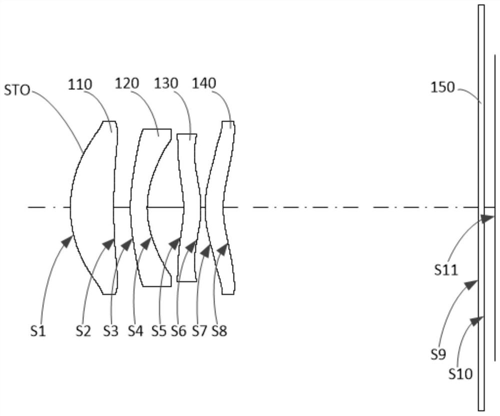
[0096] see figure 1 Embodiment 1 of the present application provides an imaging system 100. The imaging system 100 includes an aperture STO, a first lens 110, a second lens 120, a third lens 130, and a first lens arranged in sequence along the optical axis from the object side to the image side. Four lenses 140 and filters 150. The first lens 110 has positive refractive power, the second lens 120 has negative refractive power, the third lens 130 has positive refractive power, and the fourth lens 140 has positive refractive power. The object side S1 of the first lens 110 is convex at the near optical axis, and the image side S2 of the first lens 110 is concave at the near optical axis. The object side S3 of the second lens 120 is convex at the near optical axis, and the image side S4 of the second lens 120 is concave at the near optical axis. The object side S5 of the third lens 130 is concave at the near optical axis, and the image side S6 of the third lens 130 is convex at ...
Embodiment 2
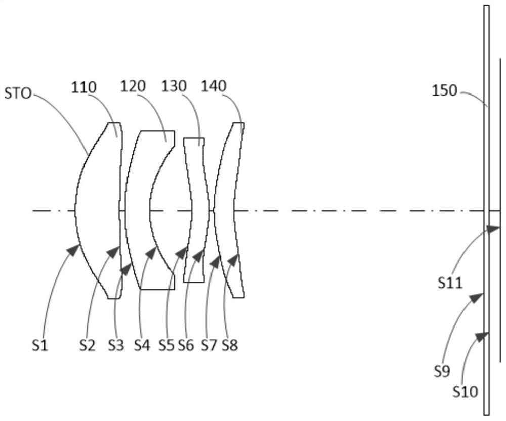
[0109] see image 3 Embodiment 2 of the present application provides an imaging system 100. The imaging system 100 includes an aperture STO, a first lens 110, a second lens 120, a third lens 130, and a second lens arranged in sequence along the optical axis from the object side to the image side. Four lenses 140 and filters 150. The first lens 110 has positive refractive power, the second lens 120 has negative refractive power, the third lens 130 has positive refractive power, and the fourth lens 140 has negative refractive power. The object side S1 of the first lens 110 is convex at the near optical axis, and the image side S2 of the first lens 110 is concave at the near optical axis. The object side S3 of the second lens 120 is convex at the near optical axis, and the image side S4 of the second lens 120 is concave at the near optical axis. The object side S5 of the third lens 130 is concave at the near optical axis, and the image side S6 of the third lens 130 is convex at...
Embodiment 3
[0118] see Figure 5Embodiment 3 of the present application provides an imaging system 100. The imaging system 100 includes a diaphragm STO, a first lens 110, a second lens 120, a third lens 130, and a second lens arranged in sequence along the optical axis from the object side to the image side. Four lenses 140 and filters 150. The first lens 110 has positive refractive power, the second lens 120 has negative refractive power, the third lens 130 has negative refractive power, and the fourth lens 140 has positive refractive power. The object side S1 of the first lens 110 is convex at the near optical axis, and the image side S2 of the first lens 110 is concave at the near optical axis. The object side S3 of the second lens 120 is convex at the near optical axis, and the image side S4 of the second lens 120 is concave at the near optical axis. The object side S5 of the third lens 130 is concave at the near optical axis, and the image side S6 of the third lens 130 is convex at...
PUM
 Abstract
Description
Claims
Application Information
 - R&D
- Intellectual Property
- Life Sciences
- Materials
- Tech Scout
- Unparalleled Data Quality
- Higher Quality Content
- 60% Fewer Hallucinations
Browse by: Latest US Patents, China's latest patents, Technical Efficacy Thesaurus, Application Domain, Technology Topic, Popular Technical Reports.
© 2025 PatSnap. All rights reserved.Legal|Privacy policy|Modern Slavery Act Transparency Statement|Sitemap|About US| Contact US: help@patsnap.com