
Whole plant waste water zero-discharge system

A zero-discharge, waste water technology, applied in water/sewage treatment, water/sludge/sewage treatment, permeation/dialysis water/sewage treatment, etc. Problems such as high equipment investment and operating costs

Inactive Publication Date: 2018-04-10
马中亮
View PDF0 Cites 1 Cited by
  • Summary
  • Abstract
  • Description
  • Claims
  • Application Information

AI Technical Summary

Problems solved by technology

[0002] Enterprises using boilers such as thermal power plants and industrial kilns discharge various types of wastewater such as circulating water sewage, industrial wastewater, coal-containing wastewater, oil-containing wastewater, and domestic wastewater. Discontinuous large-flow drainage, especially the treatment of some high-salt wastewater is difficult, and at the same time, the realization of zero discharge of large-volume wastewater requires a large equipment footprint, high equipment investment and operating costs

Method used


Image

  • Whole plant waste water zero-discharge system
  • Whole plant waste water zero-discharge system
  • Whole plant waste water zero-discharge system

Examples


Embodiment 1

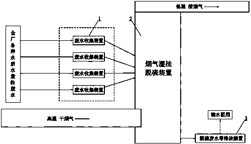
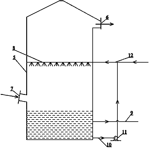
[0031] A zero-discharge system for whole plant wastewater, such as figure 1 , figure 2 As shown, it includes a waste water collection device 1 for collecting waste water from the whole plant, a flue gas wet desulfurization device 2 and a desulfurization wastewater zero discharge device 3, and the discharge pipe of the waste water collection device 1 is connected to the flue gas wet desulfurization device 2 through pipelines , the flue gas wet desulfurization device 2 is used to discharge the desulfurization waste water discharge pipe through the pipeline to connect the desulfurization waste water zero discharge device 3 . According to statistics, the evaporated water in the wastewater accounts for 60-80% of the total amount of the original wastewater.

[0032] Therefore, the waste water collection device 1 can change non-regular drainage into regular drainage to control the amount of water entering the flue gas wet desulfurization device 2 to be a stable and continuous amoun...

Embodiment 2

[0052] A system for zero discharge of waste water in the whole plant, its structure is the same as the zero discharge system of waste water in the whole plant described in embodiment 1, and the difference between it and the zero discharge system of waste water in the whole plant described in embodiment 1 is that, as Figure 6 , Figure 7 As shown, between the waste water collection device 1 and the flue gas wet desulfurization device 2, there is also a waste water cascade utilization reduction pretreatment device 4, and the discharge pipe of the waste water collection device 1 is connected to the waste water cascade utilization reduction through a pipeline. The pretreatment device 4 and the waste water cascade are connected to the flue gas wet desulfurization device 2 through pipelines using the discharge pipe of the volume reduction pretreatment device 4 . Preferably, the waste water enters the waste water cascade according to the set flow rate and flow rate and uses the redu...


PUM


Abstract

The invention discloses a system for zero discharge of waste water in the whole plant, comprising a waste water collection device (1) for collecting waste water in the whole plant, a flue gas wet desulfurization device (2) and a desulfurization waste water zero discharge device (3). The discharge pipe of the device (1) is connected to the flue gas wet desulfurization device (2) through a pipeline, and the liquid discharge pipe of the flue gas wet desulfurization device (2) used to discharge the desulfurization wastewater is connected to the desulfurization wastewater zero through the pipeline. discharge device (3). The beneficial effects of the present invention are: using the high-temperature flue gas in the flue gas wet desulfurization device to evaporate and reduce the original large amount of wastewater, so as to realize the heat utilization of the waste high-temperature flue gas and reduce the amount of wastewater treated by the zero-emission device, As a result, the land occupation, investment and operating costs of the desulfurization wastewater zero discharge device are all low.

Description

technical field [0001] The invention relates to the technical field of waste water treatment, in particular to a zero discharge system suitable for treating waste water in thermal power plants, industrial kilns and other enterprises. Background technique [0002] Thermal power plants, industrial kilns and other enterprises that use boilers discharge various waste water such as circulating water sewage, industrial waste water, coal-containing waste water, oily waste water, and domestic waste water. Discontinuous large-flow drainage, especially some high-salt wastewater is difficult to treat. At the same time, the realization of zero discharge of large-volume wastewater requires a large equipment footprint, high equipment investment and operating costs. [0003] Enterprises using boilers such as thermal power plants and industrial kilns have built flue gas desulfurization devices under the domestic "Eleventh Five-Year" environmental protection requirements, of which wet flue g...

Claims


Application Information

Patent Timeline
IPC IPC(8): C02F1/12C02F1/16C02F1/44B01D53/50
CPCC02F1/12B01D53/507C02F1/16C02F1/441
Inventor 张华朱学勤周亮程丽芬
Owner 马中亮
Learn More