Permanent magnet speed governor with fixed magnetic gap

A technology of permanent magnet speed governor and fixed magnet, which is applied in the direction of permanent magnet clutch/brake, control electromechanical brake, electric brake/clutch, etc. It can solve the problems of low energy conversion efficiency, slow adjustment speed and insensitive response, etc. Achieve the effects of fast speed regulation response, improved transmission efficiency, and reduced heat loss

Pending Publication Date: 2018-04-06
山东洁盟节能环保技术有限公司
View PDF0 Cites 0 Cited by
  • Summary
  • Abstract
  • Description
  • Claims
  • Application Information

AI Technical Summary

Problems solved by technology

Due to the use of the eddy current induction principle, the energy conversion efficiency is low, the heat generation is large, and a large amount of heat is generated during slippage
Using magnetic circuit adjustment system, the adjustment speed is slow and the response is not sensitive

Method used


Image

  • Permanent magnet speed governor with fixed magnetic gap
  • Permanent magnet speed governor with fixed magnetic gap

Examples


Embodiment Construction

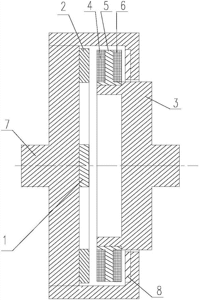
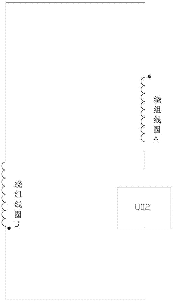
[0011] A permanent magnet governor with a fixed magnetic gap, comprising an armature rotor disc connected to an input shaft 3, a magnetic rotor disc A and a magnetic rotor disc B arranged on both sides of the armature rotor disc and connected to an output shaft 7; The armature rotor disc includes winding coil B6, winding coil A4 and iron core 5 arranged between winding coil B6 and winding coil A4 in its outer circumference and outer surface respectively. The magnetic rotor disc B is Its inner surface is provided with a permanent magnet B8 corresponding to the winding coil B6, and the magnetic rotor disk A is provided with a permanent magnet A2 corresponding to the winding coil A4 on its inner surface; the winding coil B6 and the winding coil A4 is connected in series with the same polarity, and a control system 1 for current regulation is connected in series between the two winding coils. The control system 1 is a thyristor or a MOS tube.

[0012] Preferably, the positions of...


PUM


Abstract

The invention relates to a permanent magnet speed governor with a fixed magnetic gap. The permanent magnet speed governor comprises an armature rotor disc connected to an input shaft; a magnetic rotordisc A and a magnetic rotor disc B that are disposed on both sides of the armature rotor disc and that are connected to an output shaft. The armature rotor disc includes a winding coil B and a winding coil A that are disposed inside the outer circumference thereof and the outer side surface thereof respectively, and a core disposed between the winding coil B and the winding coil A. The magnetic rotor disc B is provided with a permanent magnet B on the inner side surface thereof. The magnetic rotor disc A is provided with a permanent magnet A on the inner side surface thereof. The same polarity of the winding coil B and the winding coil A are connected in series. A control system for current regulation is connected in series between the two winding coils. Because of the armature winding, the fixed-gap permanent magnet speed governor can greatly reduce rotor heat loss, and can achieve quick, flexible and stable speed governing responses by using a current control principle so that the permanent magnet speed governor having such structure achieves greatly improved transmission efficiency and a wide application range.

Description

technical field [0001] The invention relates to a governor, in particular to a permanent magnet governor with a fixed magnetic gap. Background technique [0002] The permanent magnet speed governor uses the magnetic coupling speed of the permanent magnet to realize the soft (magnetic) connection between the motor and the load, without any harmonic generation affecting the power grid, and has high reliability. , Inflammable and explosive, voltage instability and lightning and other harsh environments, greatly reducing mechanical vibration, widely used in electric power, steel, metallurgy, petrochemical, papermaking, municipal, ships, irrigation and mining industries. At present, the commonly used permanent magnet governors realize the speed adjustment by adjusting the air gap. The magnetic circuit regulator consumes a lot of power, and has disadvantages such as poor torque transmission capability, high assembly difficulty, and waste of a large amount of rare earth resources. ...

Claims


Application Information

Patent Timeline
IPC IPC(8): H02K49/04H02K49/10H02P15/00H02P9/38
CPCH02K49/046H02K49/108H02P9/38H02P15/00
Inventor 刁俊起
Owner 山东洁盟节能环保技术有限公司
Why Eureka
Try Eureka