Test Circuits for Spacecraft

A technology for testing circuits and gate circuits, applied in the direction of measuring electricity, measuring electrical variables, instruments, etc., can solve the problems of not having multi-channel complex logic relations, and the test circuit cannot meet the requirements of spacecraft testing, etc., to achieve strong anti-interference, Guarantee the effect of service life and accuracy

Active Publication Date: 2020-09-15
BEIJING SPACE TECH RES & TEST CENT
View PDF3 Cites 0 Cited by
  • Summary
  • Abstract
  • Description
  • Claims
  • Application Information

AI Technical Summary

Problems solved by technology

However, there is no isolation means in the circuit of the existing test board, and there is no complex logic relationship of multi-channel
Therefore, none of the test circuits on the existing test boards can meet the test requirements for spacecraft

Method used


Image

  • Test Circuits for Spacecraft
  • Test Circuits for Spacecraft
  • Test Circuits for Spacecraft

Examples


Embodiment approach

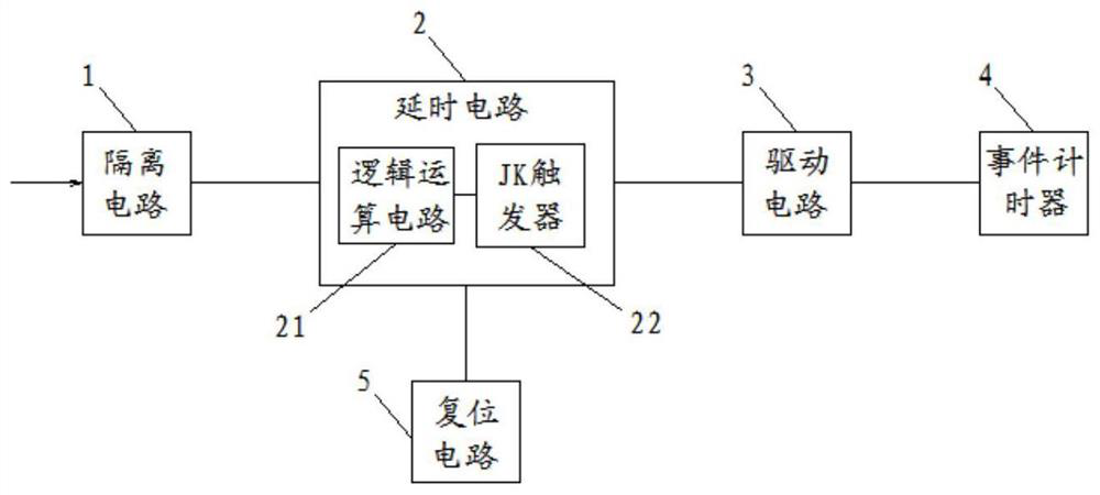
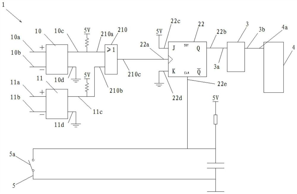
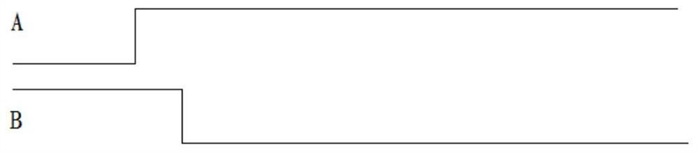
[0043] Combine figure 1 with figure 2 As shown, according to an embodiment of the present invention, the isolation circuit 1 includes a first isolation sub-circuit 10 and a second isolation sub-circuit 11. In this embodiment, the first isolator circuit 10 and the second isolator circuit 11 are independent of each other. Each independent isolator circuit receives independent input signals. Such as image 3 As shown, the first input signal A is input to the first isolating sub-circuit 10, and the second input signal B is input to the second isolating sub-circuit 11.

[0044] Combine figure 2 with image 3 As shown, the negative output terminal that outputs the first input signal A is connected to the first positive input terminal 10a of the first isolator circuit 10, and the positive output terminal that outputs the first input signal A is connected to the first isolator circuit 10 The negative input terminal 10b is connected. The positive output terminal that outputs the secon...


PUM


Abstract

The invention relates to a spacecraft test circuit comprising an isolation circuit having an input end used for receiving input signals; a delay circuit having an input end connected with the output end of the isolation circuit; a driving circuit having an input end connected to the output end of the delay circuit; an event timer having an input end connected to the output end of the driving circuit. The input signals are isolated by the isolation circuit so as to be completely isolated from subsequent circuits, thereby further ensuring the safety of the entire test circuit. By using optical-coupler isolation, the input signals are completely isolated from the circuits behind the isolation circuit. The electrical isolation between a spacecraft test point and a ground test system is achieved during the ground test of the spacecraft. The safety of the spacecraft's internal circuits is guaranteed during the ground test.

Description

Technical field [0001] The invention relates to a test circuit, in particular to a test circuit for spacecraft. Background technique [0002] During the spacecraft test, some key timing signals will be transmitted to the ground test equipment in the form of multi-channel pulse signals for measurement. The ground needs to measure the signal generation and timing of each channel. Due to spacecraft safety requirements, when testing these pulse signals, it is necessary to ensure that the spacecraft measurement points are electrically isolated from the ground test system. [0003] At present, most of the general pulse signal test circuits adopt single-channel pulse counting circuits, and the test circuits on some special pulse signal test circuits realize the counting function between multiple channels. However, there is no isolation means in the circuit of the existing test board, and there is no complex logical relationship of multiple channels. Therefore, none of the test circuits...

Claims


Application Information

Patent Timeline
Patent Type & Authority Patents(China)
IPC IPC(8): G01R31/00
CPCG01R31/00
Inventor 杨枫任亮刘武通
Owner BEIJING SPACE TECH RES & TEST CENT
Why Eureka
Try Eureka