Large-power LED radiating structure

A technology with a heat dissipation structure and high power, which is applied in lighting and heating equipment, cooling/heating devices for lighting devices, lighting devices, etc., and can solve problems such as the inability to match the use of single crystal COBLEDs, and the inability to adapt and meet the heat dissipation requirements of high-power LEDs. , to achieve the effect of improving the ability and speeding up the heat dissipation efficiency

Pending Publication Date: 2018-04-06
东莞市光引实业有限公司
View PDF6 Cites 2 Cited by
  • Summary
  • Abstract
  • Description
  • Claims
  • Application Information

AI Technical Summary

Problems solved by technology

The existing LED heat dissipation technology generally uses the riveting technology of multiple heat pipes (such as 12 heat pipes with a diameter of 8mm) to conduct heat dissipation to large-area fin groups. This technology is specially designed for polycrystalline LED lamp panels. , for example, the straight-line distance of 6 pieces with a diameter of 8mm is 48mm, which cannot be matched with single crystal COB LEDs (38*38mm)
Existing LED heat dissipation technology simply transfers heat to large-area fins, and existing LED heat dissipation modules cannot adapt to and meet the heat dissipation requirements of high-power LEDs

Method used


Image

  • Large-power LED radiating structure
  • Large-power LED radiating structure
  • Large-power LED radiating structure

Examples


Embodiment Construction

[0019] Now with reference to the accompanying drawings, the embodiments of the present invention will be described in detail.

[0020] For the sake of illustration, the width, length and thickness of certain components in the schematic diagrams are sometimes exaggerated.

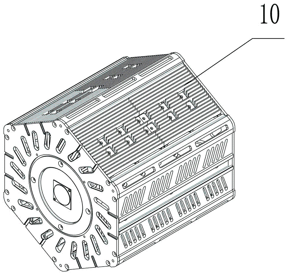
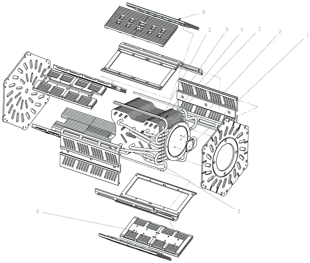
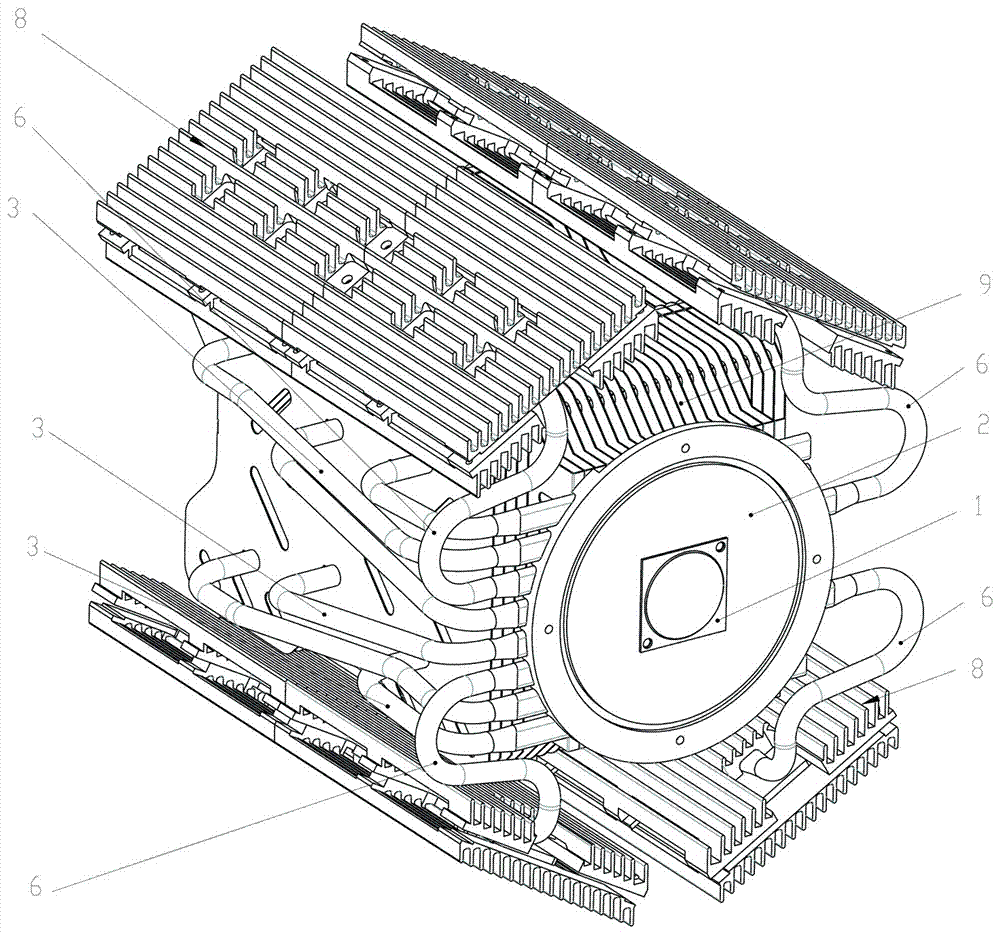
[0021] Such as Figure 1 to Figure 4 As shown, a high-power LED heat dissipation structure includes a housing 10, a heat dissipation bottom plate 2 bonded to an LED heat source 1, a heat pipe, and heat dissipation fins 9. The housing 10 includes a heat dissipation plate 8 with a heat dissipation groove 11, The heat dissipation fins 9 are disposed in the cavity enclosed by the housing 10 . The heat pipes are divided into two types. The first heat pipe 6 is connected to the heat dissipation base plate 2 such as welding, and extends axially in the heat dissipation plate 8. In this embodiment, the heat dissipation plate 8 has two layers. The first type of heat pipe 6 is arranged between two layers of heat diss...


PUM


Abstract

The invention relates to a large-power LED radiating structure. The large-power LED radiating structure comprises a shell, a radiating bottom plate attached to an LED heat source, heat-conducting pipes and radiating fins. The shell comprises radiating plates with radiating grooves; the radiating fins are arranged in a cavity defined by the shell; the heat-conducting pipes are divided into the first heat-conducting pipes and the second heat-conducting pipes; the first heat-conducting pipes are connected with the radiating bottom plate and extend in the axial direction in the radiating plates; and one ends of the second heat-conducting pipes are connected with the radiating bottom plate, and the other ends of the second heat-conducting pipes penetrate through the radiating fins. Compared with the prior art, according to the large-power LED radiating structure, heat on a radiating base is conducted to the radiating fins and the radiating plates on the shell of the radiating structure, andthe exchange speeds of hot air in the different directions are different, so that the radiating efficiency can be improved, and the natural convection radiating capability is promoted.

Description

technical field [0001] The invention relates to a high-power LED heat dissipation technology, in particular to a high-power LED heat dissipation structure of a surface light source. Background technique [0002] COB is the abbreviation of chip On board. It is to adhere the bare chip to the interconnection substrate with conductive or non-conductive adhesive, and then perform wire bonding to realize its electrical connection. COB LED is also called COB LED light source and COB LED module. Since the advent of COB LEDs to the present, heat dissipation has always been the biggest issue. In the early COB LEDs, because the photoelectric conversion technology stayed at 20% light and 80% heat, COB LEDs have been unable to achieve high-power applications. In recent years, COB LEDs have been used in packaging Technological breakthroughs have improved the luminous efficiency of COB LEDs, and some manufacturers have begun to improve heat dissipation, so that the application of COB LED...

Claims


Application Information

Patent Timeline
Patent Type & Authority Applications(China)
IPC IPC(8): F21V29/503F21V29/71F21V29/76F21V29/89F21Y115/10
CPCF21V29/503F21V29/717F21V29/76F21V29/89F21Y2115/10
Inventor 卓圣国张顺来
Owner 东莞市光引实业有限公司
Why Eureka
Try Eureka