Flattening equipment for cardboard bonding
A paper shell and equipment technology, which is applied in the field of flattening equipment for paper shell bonding, can solve the problems of easy adhesion of debris, time-consuming and laborious, and poor flattening effect.
- Summary
- Abstract
- Description
- Claims
- Application Information
AI Technical Summary
Problems solved by technology
Method used
Image


Examples
Embodiment 1
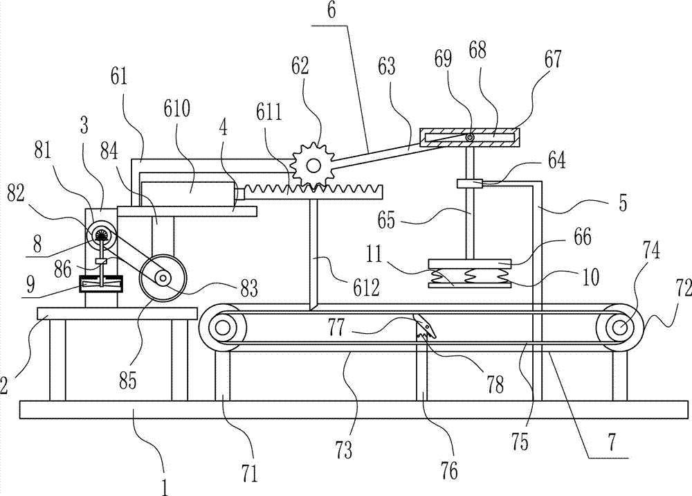
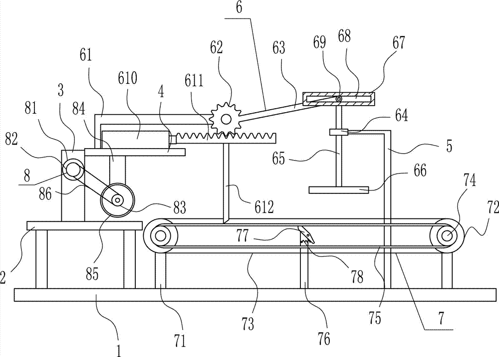
[0037] A flattening device for paper shell bonding, such as Figure 1-7 As shown, it includes a bottom plate 1, a placement table 2, a mounting plate 3, a horizontal plate 4, a 7-shaped rod 5, a flattening device 6 and a conveying device 7. The top left side of the bottom plate 1 is equipped with a placement table 2. A mounting plate 3 is installed on the side, a horizontal plate 4 is installed on the upper right side of the mounting plate 3, a conveying device 7 is arranged on the top right side of the bottom plate 1, a 7-type rod 5 is installed on the right side of the top of the bottom plate 1, and the 7-type rod 5 is located on the conveying device 7. On the rear side, a flattening device 6 is provided between the tail end of the 7-shaped rod 5 and the top of the horizontal plate 4. The flattening device 6 is located above the conveying device 7. The moving parts of the flattening device 6 contact the driving parts of the conveying device 7.
Embodiment 2
[0039] A flattening device for paper shell bonding, such as Figure 1-7 As shown, it includes a bottom plate 1, a placement table 2, a mounting plate 3, a horizontal plate 4, a 7-shaped rod 5, a flattening device 6 and a conveying device 7. The top left side of the bottom plate 1 is equipped with a placement table 2. A mounting plate 3 is installed on the side, a horizontal plate 4 is installed on the upper right side of the mounting plate 3, a conveying device 7 is arranged on the top right side of the bottom plate 1, a 7-type rod 5 is installed on the right side of the top of the bottom plate 1, and the 7-type rod 5 is located on the conveying device 7. On the rear side, a flattening device 6 is provided between the tail end of the 7-shaped rod 5 and the top of the horizontal plate 4. The flattening device 6 is located above the conveying device 7. The moving parts of the flattening device 6 contact the driving parts of the conveying device 7.
[0040] The flattening device ...
Embodiment 3
[0042] A flattening device for paper shell bonding, such as Figure 1-7 As shown, it includes a bottom plate 1, a placement table 2, a mounting plate 3, a horizontal plate 4, a 7-shaped rod 5, a flattening device 6 and a conveying device 7. The top left side of the bottom plate 1 is equipped with a placement table 2. A mounting plate 3 is installed on the side, a horizontal plate 4 is installed on the upper right side of the mounting plate 3, a conveying device 7 is arranged on the top right side of the bottom plate 1, a 7-type rod 5 is installed on the right side of the top of the bottom plate 1, and the 7-type rod 5 is located on the conveying device 7. On the rear side, a flattening device 6 is provided between the tail end of the 7-shaped rod 5 and the top of the horizontal plate 4. The flattening device 6 is located above the conveying device 7. The moving parts of the flattening device 6 contact the driving parts of the conveying device 7.
[0043] The flattening device ...
PUM
 Abstract
Description
Claims
Application Information
 - R&D
- Intellectual Property
- Life Sciences
- Materials
- Tech Scout
- Unparalleled Data Quality
- Higher Quality Content
- 60% Fewer Hallucinations
Browse by: Latest US Patents, China's latest patents, Technical Efficacy Thesaurus, Application Domain, Technology Topic, Popular Technical Reports.
© 2025 PatSnap. All rights reserved.Legal|Privacy policy|Modern Slavery Act Transparency Statement|Sitemap|About US| Contact US: help@patsnap.com