
Pump pipe gluing device in blood pipeline

A viscose and pump tube technology, which is applied to devices and coatings that apply liquid to the surface, can solve the problems of easy white marks, uncontrollable cyclohexanone amount, and easy flow of glue on the pump tube bone. Splashing glue, solving the effect of incomplete glue and white printing

Pending Publication Date: 2018-04-06
贝恩医疗设备(广州)有限公司
View PDF8 Cites 1 Cited by
  • Summary
  • Abstract
  • Description
  • Claims
  • Application Information

AI Technical Summary

Problems solved by technology

However, this simple glue device has the following disadvantages: when the end face of the pump tube is manually pressed into the sponge, the glue in the sponge splashes into the inner wall of the pump tube, which easily causes glue to flow inside the bone of the pump tube; when the operator repeats the operation, If the operation method is not controlled, the glue on the side of the pump tube will be incomplete and easy to have white marks, and the length of the glue on the side is not uniform, and the duration is short; the amount of cyclohexanone in the sponge is uncontrollable, resulting in an uncontrollable amount of glue

Method used


Image

  • Pump pipe gluing device in blood pipeline
  • Pump pipe gluing device in blood pipeline
  • Pump pipe gluing device in blood pipeline

Examples


Embodiment 1

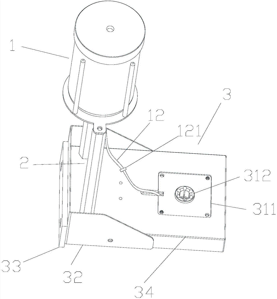
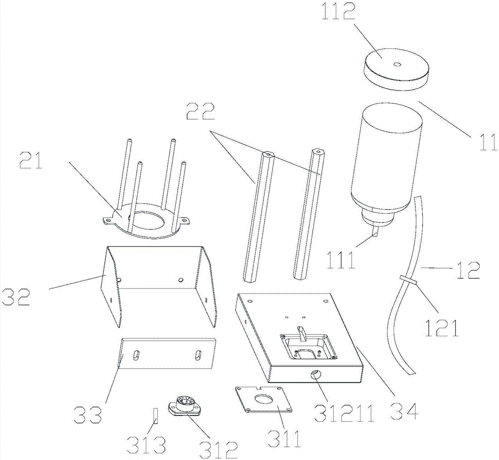
[0050] A pump tube adhesive device in a blood line, such as Figures 1 to 6 As shown, a viscose mechanism 3 for making the outer wall of the pump tube stick with viscose, a viscose liquid storage mechanism 1 and a support mechanism 2 for storing the viscose, the support mechanism 2 is fixedly installed above the viscose mechanism 3, The liquid storage mechanism 1 is assembled on the support mechanism 2 . The liquid storage mechanism 1 allows the glue liquid to enter the glue mechanism 3 through the conduit 12 .

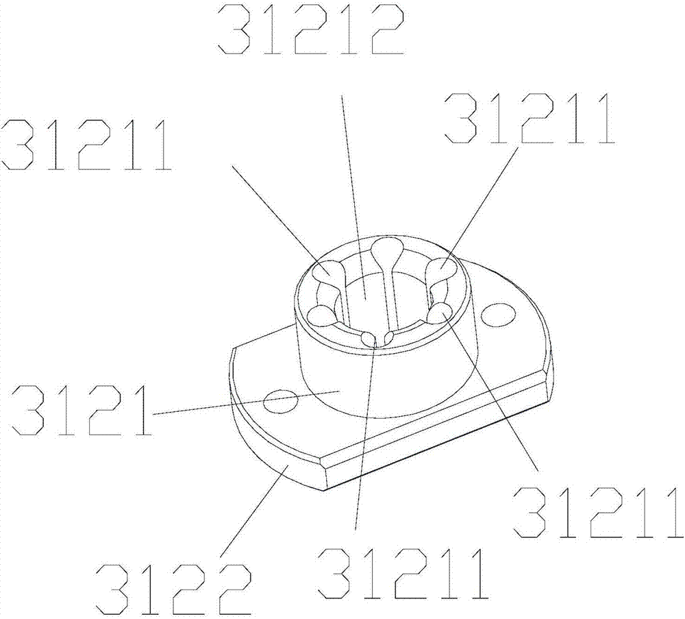
[0051] The gluing mechanism 3 is provided with a gluing part 31 and a gluing base 34 , and the gluing part 31 is embedded in the gluing base 34 . The adhesive part 31 is provided with an adhesive ring 312, a cover plate 311 matched with the adhesive ring 312, and an absorber 313. The absorber 313 is detachably embedded in the adhesive ring 312, and the adhesive ring 312 is embedded in the cover plate 311 and is connected to the cover plate 311. The viscose seat body...


PUM


Abstract

Disclosed is a pump pipe gluing device in a blood pipeline. The pump pipe gluing device in the blood pipeline is provided with a gluing mechanism used for gluing mucilage glue liquid on the outside wall of the pimp pipe, a liquid storage mechanism used for storing the mucilage glue liquid, and a supporting mechanism. The supporting mechanism is fixed above the gluing mechanism, and the liquid storage mechanism is arranged on the supporting mechanism. The mucilage glue liquid in the liquid storage mechanism enters into the gluing mechanism by a guiding pipe. The pump pipe gluing device in the blood pipeline has the following beneficial effects that the mucilage glue liquid in the gluing mechanism is always in a flow condition to ensure that the mucilage glue liquid in an absorber is alwaysin a saturation condition, so that the quantity of the gluing can be controlled effectively; the insertion depth of the pimp pipe can be fixed by the gluing mechanism, and the gluing length of the side surface of the pump pipe is controlled; a plurality of absorbers are embedded into a gluing portion so as to ensure that gluing in the side surface of the pump pipe can be complete when the pump pipe rotates, and the problems of incomplete gluing and white seal are solved; the end portion of the pump pipe can not straightly be inserted into the liquid level of the glue mucilage to prevent the glue of the inside wall of the pump pipe splashing.

Description

technical field [0001] The invention relates to blood tube production equipment, in particular to a pump tube adhesive device in the blood tube. Background technique [0002] In the prior art, the pump tube glue of the blood line is to place cyclohexanone in a small box, place a sponge in the box, and use the water absorption performance of the sponge to absorb the cyclohexanone in the sponge. When working in the pump tube gluing process, first press the end face of the pump tube into the sponge so that the end face of the pump tube is glued with glue, and then rotate the side of the pump tube on the sponge to make the outside of the pump tube stick with glue. However, this simple glue device has the following disadvantages: when the end face of the pump tube is manually pressed into the sponge, the glue in the sponge splashes into the inner wall of the pump tube, which easily causes glue to flow inside the bone of the pump tube; when the operator repeats the operation, If ...

Claims


Application Information

Patent Timeline
Patent Type & Authority Applications(China)
IPC IPC(8): B05C13/02B05C11/11B05C11/10
CPCB05C11/10B05C11/11B05C13/02
Inventor 廖磊
Owner 贝恩医疗设备(广州)有限公司
Learn More