Eureka AIR delivers breakthrough ideas for toughest innovation challenges, trusted by R&D personnel around the world.

Ceramic catalytic filter element for flue gas purification and flue gas desulfurization and denitrification integrated dust removal method

A flue gas purification, desulfurization and denitrification technology, which is applied in the field of flue gas purification, can solve the problems of loss of denitrification catalyst supported by substrate ceramic materials, short service life and replacement cycle, and reduced denitrification efficiency, so as to increase catalytic active sites and prolong The effect of service life and improvement of denitrification efficiency

Active Publication Date: 2018-04-06
济南玉泉生物发电有限公司
View PDF4 Cites 13 Cited by
  • Summary
  • Abstract
  • Description
  • Claims
  • Application Information

AI Technical Summary

Problems solved by technology

However, due to the limitation of the physical characteristics of the ceramic filter element itself, the loading amount of the denitrification catalyst in the inner layer of the filter element is small, and the residence time of the flue gas passing through the filter element is short, resulting in low denitrification efficiency; and due to the periodic change of the airflow direction (The ceramic filter element needs to be blown back to control the excessive pressure drop) The thermal shock, thermal fatigue, etc. caused by the regeneration of the ceramic catalytic filter element, the physical damage of the base ceramic material and the loss or failure of the loaded denitrification catalyst further reduce the Its denitrification efficiency leads to short service life and replacement cycle, high operating cost, and cannot meet the requirements of actual industrial applications.

Method used


Image

  • Ceramic catalytic filter element for flue gas purification and flue gas desulfurization and denitrification integrated dust removal method

Examples

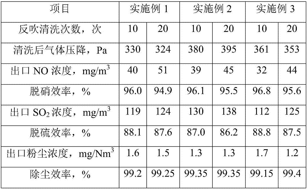

Embodiment 1

[0040] The ceramic catalytic filter element for flue gas purification in this embodiment is prepared by a method comprising the following steps:

[0041] 1) Take a microporous alumina ceramic filter tube with a pore size of 40-60 μm, and use a mixture of ethanol and water with a volume ratio of 1:1 to perform ultrasonic cleaning, dry it at 80°C after cleaning, and use it as a substrate for later use;

[0042] 2) According to the molar ratio of ethylene glycol methyl ether and ethanolamine, the mixed solvent is prepared in a ratio of 1:0.2;

[0043] Take zinc acetate dihydrate, add it to the mixed solvent, and stir at 60°C for 2 hours to prepare a mixed sol with a zinc acetate concentration of 0.3mol / L;

[0044] 3) Immerse the matrix in step 1) into the mixed sol obtained in step 2), and immerse under negative pressure for 0.5 h until the pores of the matrix are saturated with adsorption; after taking out the matrix, scrape off the remaining impregnating liquid on the inner and...

Embodiment 2

[0054] The ceramic catalytic filter element for flue gas purification in this embodiment is prepared by a method comprising the following steps:

[0055] 1) Take a microporous alumina ceramic filter tube with a pore size of 50-70 μm, and use a mixture of ethanol and water with a volume ratio of 1:1 to perform ultrasonic cleaning, dry it at 80°C after cleaning, and use it as a substrate for later use;

[0056] 2) According to the molar ratio of ethylene glycol methyl ether and ethanolamine, a mixed solvent is prepared in a ratio of 1:0.3;

[0057] Take zinc acetate dihydrate, add it to the mixed solvent, and stir at 65°C for 1.5h to prepare a mixed sol with a zinc acetate concentration of 0.4mol / L;

[0058] 3) Immerse the matrix in step 1) into the mixed sol obtained in step 2), and immerse under negative pressure for 1 hour until the pores of the matrix are absorbed and saturated; after taking out the matrix, scrape off the remaining impregnating liquid on the inner and outer ...

Embodiment 3

[0068] The ceramic catalytic filter element for flue gas purification in this embodiment is prepared by a method comprising the following steps:

[0069] 1) Take a microporous alumina ceramic filter tube with a pore size of 40-60 μm, and use a mixture of ethanol and water with a volume ratio of 1:1 to perform ultrasonic cleaning, dry it at 80°C after cleaning, and use it as a substrate for later use;

[0070] 2) According to the molar ratio of ethylene glycol methyl ether and ethanolamine, the mixed solvent is prepared in a ratio of 1:0.4;

[0071] Take zinc acetate dihydrate, add it to the mixed solvent, and stir at 70°C for 1 hour to prepare a mixed sol with a concentration of zinc acetate of 0.5mol / L;

[0072] 3) Immerse the matrix in step 1) into the mixed sol obtained in step 2), and immerse under negative pressure for 1 hour until the pores of the matrix are absorbed and saturated; after taking out the matrix, scrape off the remaining impregnating liquid on the inner and...


PUM

PropertyMeasurementUnit
pore sizeaaaaaaaaaa
thicknessaaaaaaaaaa
pore sizeaaaaaaaaaa

Abstract

The invention relates to a ceramic catalytic filter element for flue gas purification and a flue gas desulfurization and denitrification integrated dust removal method. The ceramic catalytic filter element is prepared from the following steps that a microporous alumina ceramic filter tube with a pore diameter of 40-80 microns is taken as a matrix; the matrix is immersed in a mixed sol made of zincacetate, and after the matrix is impregnated under a negative pressure, the matrix is roasted to obtain a modified matrix modified by zinc oxide; an equal volume impregnation method is adopted, and the modified matrix is impregnated with an mixed oxalic acid solution containing ammonium metavanadate and ammonium metatungstate, so that total loading mass of V2O5 and WO3 in pores of the matrix reaches 4.0%-6.0% to obtain an active matrix; the active matrix is immersed in a mixed sol made of Al2O3-SiO2-TiO2, the active matrix is dried and roasted after the active matrix is taken out, and a densefilm with a thickness of 0.2-0.6 millimeter and a pore diameter of 1-10 microns is formed on the outer surface of the active matrix to obtain the ceramic catalytic filter element. A denitrification catalyst of the ceramic catalytic filter element has the advantages of being strong in load, high in denitrification efficiency, long in service life and applicable to popularizing and using.

Description

technical field [0001] The invention belongs to the technical field of flue gas purification, specifically relates to a ceramic catalytic filter element for flue gas purification, and also relates to an integrated flue gas desulfurization, denitrification and dust removal method using the ceramic catalytic filter element. Background technique [0002] With the development of society and people's emphasis on air quality, the state has put forward stricter standards for the concentration of pollutants produced by fuel combustion. At present, the flue gas purification system at the tail of a large-scale combustion device is generally composed of a flue gas denitrification device, a dust removal device, and a flue gas desulfurization device. The defects of high cost and large floor area hinder the promotion and implementation of flue gas purification technology to a certain extent. Therefore, in order to reduce costs, the combined removal technology that can simultaneously puri...

Claims


Application Information

Patent Timeline
Patent Type & Authority Applications(China)
IPC IPC(8): B01J23/30B01D39/20B01D53/86B01D53/82B01D53/60B01D46/54B01D53/68B01D46/00
CPCB01D39/2068B01D46/543B01D53/82B01D53/8637B01D53/8659B01J23/30B01D2239/10B01D2251/2062B01D2255/20723B01D2255/20776B01D2255/20707B01D2255/20792B01D2255/2092B01D2255/30B01D2253/112B01D46/70
Inventor 李建州
Owner 济南玉泉生物发电有限公司
Why Eureka
Eureka Blog
Learn More