
Shake-up device

A technology for installing plates and containers, which is applied in the field of medical devices, can solve the problems of narrow application range, slow shaking speed, and poor shaking effect, and achieve the effect of wide application range, fast shaking speed, and good effect

Pending Publication Date: 2018-04-03
苏州立禾生物医学工程有限公司
View PDF0 Cites 1 Cited by
  • Summary
  • Abstract
  • Description
  • Claims
  • Application Information

AI Technical Summary

Problems solved by technology

[0005] The technical problem to be solved by the present invention is: the shaking effect of the existing shaking device is not good, the shaking speed is slow, and the problem of narrow application range

Method used


Image

  • Shake-up device
  • Shake-up device
  • Shake-up device

Examples


Embodiment 1

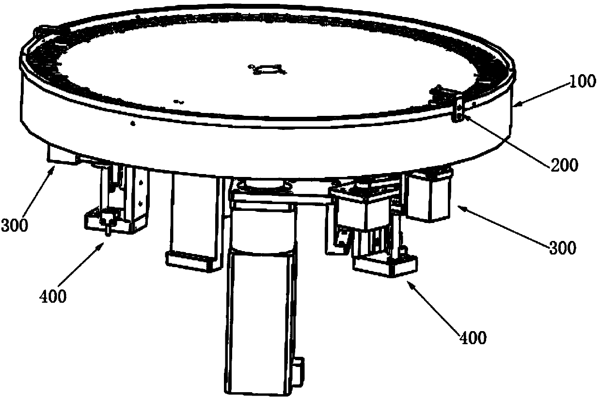
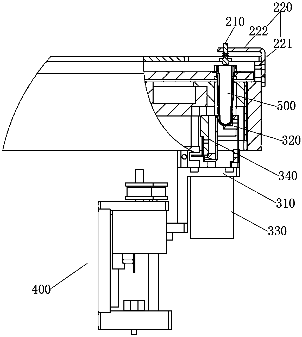
[0039] This embodiment provides a shaking device, such as figure 1 and 2 As shown, it includes a lifting mechanism 400, a shaking mechanism 300 and a container positioning mechanism 200. The lifting mechanism 400 controls the lifting of the shaking mechanism 300, and the reactant container (reaction cup 500 in this embodiment) placed on the reaction disk 100 Hold it up to the container positioning mechanism 200, and then shake the reactants in the cuvette 500 evenly. Wherein, the container positioning mechanism 200 is arranged above the cuvette 500, and includes a positioning column 210 and a positioning column fixing plate 220. The positioning column fixing plate 220 includes a vertical rod 221 and a cross arm 222. The vertical rod 221 is fixed on the reaction disk 100. The positioning column 210 is located below the cross arm 222 , above the cuvette 500 at the reaction position, and opposite to the upper port of the cuvette 500 . When the cuvette 500 is supported by the sh...

Embodiment 2

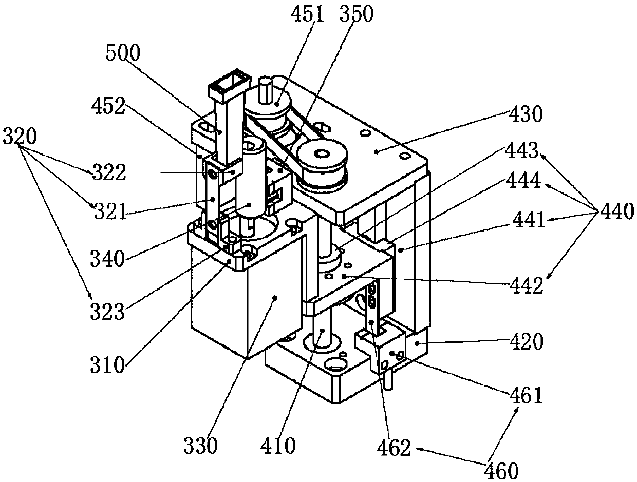
[0048] Such as image 3 As shown, this embodiment provides a preferred lifting mechanism 400 on the basis of Embodiment 1, including a lifting screw 410 , a screw bottom plate 420 , a screw upper plate 430 , a lifting rail assembly 440 and a synchronous pulley set 451 . Wherein, the bottom plate 420 of the screw rod is arranged at the lower end of the lifting screw rod 410 , and the upper plate 430 of the screw rod is arranged at the upper end of the lifting screw rod 410 . The lifting guide rail assembly 440 includes a slider group and a guide rail plate 441 standing between the screw upper plate 430 and the screw bottom plate 420. The slider group is installed on the lifting screw 410 through a screw nut 443. The shaking mechanism 300 The mounting plate 310 is fixedly connected with the slider group. The synchronous pulley group 451 is arranged on the upper plate 430 of the screw mandrel or the bottom plate 420 of the screw mandrel, the rotating shaft of its driving wheel i...


PUM


Abstract

The invention relates to a shake-up device for uniform mixing of reactants. The shake-up device comprises lifting mechanisms, shake-up mechanisms and container positioning mechanisms, wherein each shake-up mechanism is provided with an elastic assembly for jacking up a reactant container, an eccentric shaft assembly for pushing the reactant container to swing back and forth as well as a shake-up photoelectric sensing assembly for detecting the rotating state of the eccentric shaft assembly. The eccentric shaft assemblies are arranged beside the reactant containers to drive the reactant containers to swing back and forth, so that the shake-up effect of the reactants is better; the shake-up photoelectric sensing assemblies can feed back frequency for swing of the reactant containers, and theswing speed can be controlled and adjusted according to demands of different reactants; a zero-position detection assembly is added to each lifting mechanism, lifting height is controlled through a synchronous pulley group and can be set according to different heights of different models of the reactant containers, so that the shake-up device can be applied to shake-up operation of various modelsof the reactant containers and is wide in application range, and the cost is saved.

Description

technical field [0001] The invention relates to a shaking device for shaking reactants, which belongs to the technical field of medical devices. Background technique [0002] Immunoassay is an important means of clinical diagnosis and treatment, including viruses, hormones, tumor markers and other detection items. It has the advantages of high sensitivity, wide detection range, and good stability of markers, and has become the most important means of in vitro immune detection. . [0003] The detection and analysis process of the fully automatic chemiimmunity machine designed based on the chemiluminescence mechanism mainly includes four steps: sample addition-incubation-cleaning-measurement. Among them, the automation of sample addition is the core of the instrument, including automatic sample dilution and sample addition, direct sample addition of reaction reagents or even sample addition after dilution, mixing of reactants with magnetic beads, and release of magnetic beads...

Claims


Application Information

Patent Timeline
IPC IPC(8): G01N1/38G01N1/28
CPCG01N1/286G01N1/38
Inventor 申峰波周方芳田阳徐炯宽
Owner 苏州立禾生物医学工程有限公司
Learn More