
Combined transformer

A combined transformer and transformer technology, applied in the direction of transformer/inductor parts, transformer/inductor coil/winding/connection, electrical component structure association, etc. Volume, the effect of reducing the overall size

Pending Publication Date: 2018-03-30
HENAN SENYUAN ELECTRIC CO LTD
View PDF19 Cites 3 Cited by
  • Summary
  • Abstract
  • Description
  • Claims
  • Application Information

AI Technical Summary

Problems solved by technology

[0005] The purpose of the present invention is to provide a combined transformer to solve the problem of large volume of the transformer oil tank of the lead wire structure of the photovoltaic transformer in the prior art

Method used


Image

  • Combined transformer
  • Combined transformer
  • Combined transformer

Examples


Embodiment Construction

[0023] Embodiments of the present invention will be further described below in conjunction with the accompanying drawings.

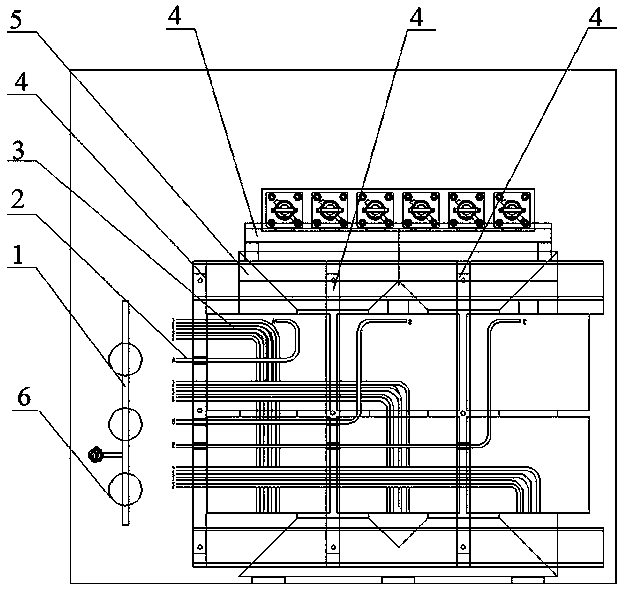
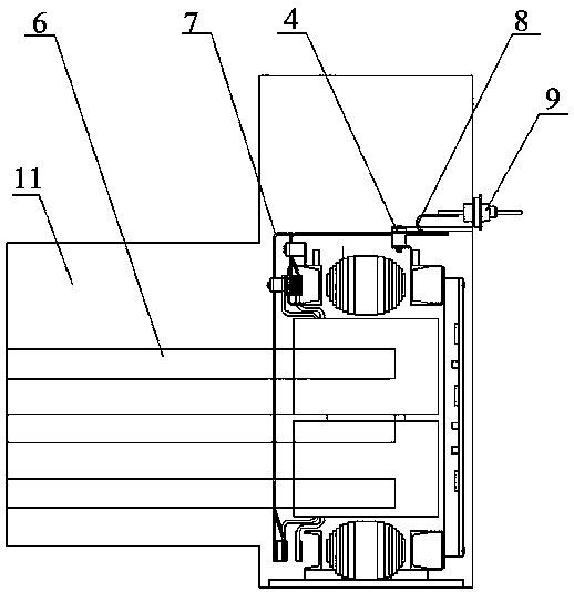
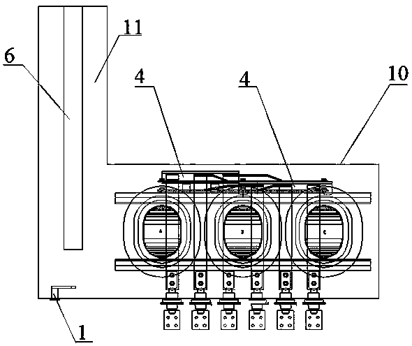
[0024] Embodiment 1 of the combined transformer of the present invention, as Figure 1 to Figure 3 As shown, the combined transformer includes a transformer oil tank 10, and the transformer oil tank 10 is provided with a transformer body 5, a high-voltage fuse 6 and a low-voltage terminal 9, and the transformer body 5 has a high-voltage main lead 2, a high-voltage tap lead 3 and a low-voltage lead 7 , The left side of the transformer body 5 is provided with a tap switch 1 . The high-voltage main lead wire 2 is connected from the high-voltage coil to the incoming terminal of the high-voltage fuse 6, connected from the outgoing terminal of the high-voltage fuse 6 to the incoming terminal of the load switch, and introduced into the high-voltage bushing from the outgoing terminal of the load switch; the high-voltage tap lead 3 Connected to the tap changer 1...


PUM


Abstract

The invention relates to a combined transformer. The combined transformer comprises a transformer oil tank, a transformer body is arranged in the transformer oil tank, a tap-changer is arranged on oneside of the left or the right of the transformer body, the combined transformer further includes a high voltage fuse installed on the same side with the tap-changer, and the high voltage fuse stretches along forward and backward directions. The high voltage fuse of the combined transformer is arranged on one side of the left or the right of the transformer body, the upper space of the oil tank isnot occupied by the high voltage fuse, accordingly the height of the transformed oil tank is lowered, and the high voltage fuse is installed on the same side with the tap-changer, the inner space ofthe oil tank is sufficiently used, the overall size of the oil tank is reduced, accordingly the cost of the transfer oil tank is reduced.

Description

technical field [0001] The invention relates to a combined transformer. Background technique [0002] With the development of new energy technology in China, more and more transformers are used for photovoltaic power generation. Photovoltaic power generation mainly adopts combined transformers. There are many internal components in combined transformers, and the layout of lead wires is relatively complicated. The overall volume of combined transformers is relatively large, and the manufacturing cost is relatively high. [0003] The Chinese patent application with the publication number CN105097231A and the publication date of 2015.11.25 discloses a photovoltaic transformer lead wire structure. The photovoltaic transformer lead wire structure includes a body, which is a transformer body. A fuse is installed, and the transformer body is divided into two sides, namely the high-voltage side and the low-voltage side. The high-voltage side has a high-voltage main lead, and the hi...

Claims


Application Information

Patent Timeline
Patent Type & Authority Applications(China)
IPC IPC(8): H01F27/40H01F27/29
CPCH01F27/292H01F27/402H01F2027/404
Inventor 王培张海峰孙银龙
Owner HENAN SENYUAN ELECTRIC CO LTD
Learn More