
A display panel control method

A display panel and control method technology, applied to static indicators, instruments, etc., can solve problems such as vertical stripes on high PPI display panels

Active Publication Date: 2021-08-03
WUHAN TIANMA MICRO ELECTRONICS CO LTD
View PDF0 Cites 0 Cited by
  • Summary
  • Abstract
  • Description
  • Claims
  • Application Information

AI Technical Summary

Problems solved by technology

[0007] In view of this, the present invention provides a display panel control method to solve the problem of vertical stripes on the high PPI display panel when direct charging is used to charge and display sub-pixels in the prior art

Method used


Image

  • A display panel control method
  • A display panel control method
  • A display panel control method

Examples


Embodiment Construction

[0032] As mentioned in the background section, the direct charging method in the prior art will cause vertical stripes to appear on the display panel.

[0033] The inventors found that the reason for the above problems is that when using the direct charging method to charge the sub-pixels, the charging time of each column of data lines is different. For details, please refer to Figure 5 As shown, it is a control timing diagram of a 1:6 demux circuit provided by the prior art; during direct charging, since the data writing time of each column of subpixels is different, the brightness of each column of subpixels is different. When displaying, It will show unevenness. For example, the data writing time on the data line controlled by CKH1 is the earliest, and its charging time is the longest T1. The subsequent data writing time on the data lines controlled by CKH2, CKH3, CKH4, CKH5, and CKH6 is delayed in turn. The length of a turn-on time, the corresponding charging time is grad...


PUM


Abstract

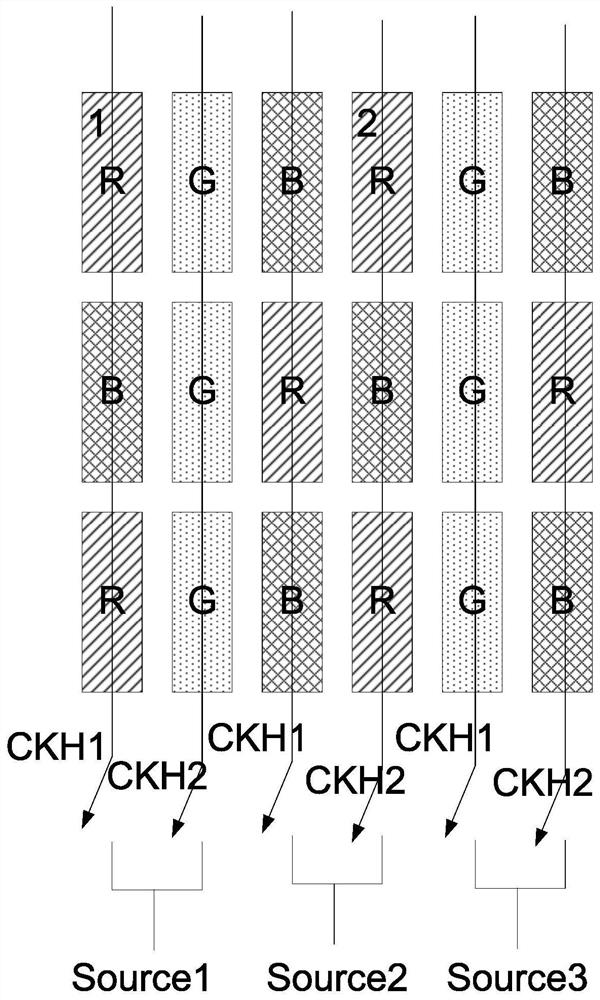
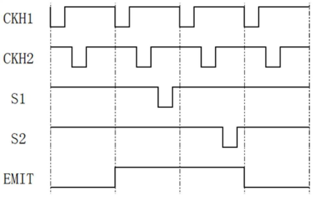
The present application provides a method for controlling a display panel. The display panel includes: a plurality of gate lines, a plurality of data lines arranged to insulate and intersect with the gate lines, and a plurality of sub-pixels arranged in an array; charge a plurality of sub-pixels with different colors The N data lines are connected to a signal input terminal through a demultiplexer, wherein, N is an integer greater than 1; the control method includes: using a direct charge method to charge multiple sub-pixels connected to the demultiplexer; wherein, in In the preset cycle, the charging time of sub-pixels of the same color is the same. By changing the order of data writing time on the data line in each demux circuit in the preset period, the charging time of sub-pixels with the same color is the same, thereby avoiding the same charging time on each column, and the column and The charging time between the columns is different, causing the problem of vertical stripes on the display panel.

Description

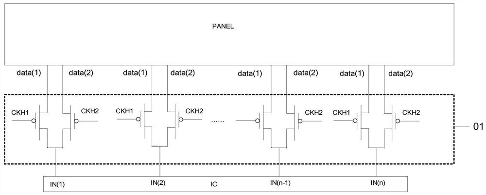
technical field [0001] The present invention relates to the field of display technology, in particular to a method for controlling a display panel. Background technique [0002] At present, a display device generally includes a display panel and a driving circuit. In the display panel, a plurality of sub-pixels are arranged in a matrix. The driving circuit includes a gate driving circuit for driving gate lines and a data driving circuit for driving data lines. In order to reduce the cost of the display device, it is generally desired to reduce the number of output channels of the data driving circuit while maintaining the resolution. Based on this, if figure 1 As shown, in the display panel, a demux (Demux) 01 will be used to connect every two data lines to a data signal input terminal IN(1), IN(2)...or IN(n), and a data signal The input end is connected with an output channel of the data driving circuit, so that the output channel of the data driving circuit can be reduce...

Claims


Application Information

Patent Timeline
Patent Type & Authority Patents(China)
IPC IPC(8): G09G3/20
CPCG09G3/20G09G3/3275G09G2300/0819G09G2310/0251G09G2310/0297G09G3/2003G09G2310/0205G09G2300/0861
Inventor 李玥朱仁远向东旭高娅娜周星耀
Owner WUHAN TIANMA MICRO ELECTRONICS CO LTD
Learn More