
Display panel and display device

A display panel and display area technology, applied in static indicators, instruments, etc., can solve the problems of reducing the width of the frame, occupying a large space of the chip on film, disadvantage, etc., to reduce the number, avoid vertical stripes, and turn on time. small difference effect

Active Publication Date: 2020-09-25
WUHAN TIANMA MICRO ELECTRONICS CO LTD
View PDF5 Cites 0 Cited by
  • Summary
  • Abstract
  • Description
  • Claims
  • Application Information

AI Technical Summary

Problems solved by technology

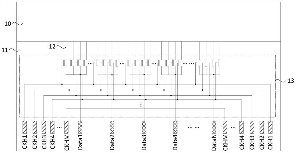
[0003] However, the DEMUX circuit decomposes one signal channel into more signal channels. Therefore, more clock control signals CKH are required. Since the clock control signals CKH of the existing DEMUX circuit are driven by both sides, more clock control signals CKH are required. Therefore, a wider chip-on-film (COF) is needed to bind the signal line of CKH to the driver chip, so that the chip-on-chip film takes up a large space, which is not conducive to reducing the width of the frame

Method used


Image

  • Display panel and display device
  • Display panel and display device
  • Display panel and display device

Examples


Embodiment Construction

[0029] The present invention will be further described in detail below in conjunction with the accompanying drawings and embodiments. It should be understood that the specific embodiments described here are only used to explain the present invention, but not to limit the present invention. In addition, it should be noted that, for the convenience of description, only some structures related to the present invention are shown in the drawings but not all structures.

[0030] figure 1 It is a structural schematic diagram of an existing display panel. see figure 1 , the display panel includes a display area 10 and a non-display area 11, the display area 10 includes a plurality of sub-pixels arranged in an array and data lines 12 connected to the same column of sub-pixels, and the non-display area 11 includes a DEMUX circuit 13. Take the DEMUX circuit 13 where M selects 1 as an example, the DEMUX circuit 13 connects each M data lines 12 to a data signal input terminal Data1, Dat...


PUM


Abstract

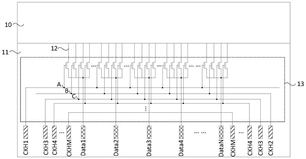
The invention discloses a display panel and a display device. The display panel comprises a multi-path selection circuit, a data signal source terminal and a gating signal output terminal, and the multipath selection circuit comprises a plurality of switch circuit groups. Each switching circuit comprises a gating signal receiving terminal and a data signal output terminal; the gating signal outputterminals comprise a first type gating signal output terminal and / or a second type gating signal output terminal; the first type gating signal output terminal and the second type gating signal outputterminal are positioned on different sides of the data signal source terminal; sub-pixels emitting light of the same color are electrically connected with a plurality of data signal output terminalsin the same switching circuit group through data lines, and gating signal receiving terminals of at least one switching circuit group are electrically connected with the first type gating signal output terminal or electrically connected with the second type gating signal output terminal. According to the display panel and the display device provided by the invention, the number of channels is reduced, and meanwhile, the problem of vertical stripes is solved.

Description

technical field [0001] Embodiments of the present invention relate to the field of display technology, and in particular, to a display panel and a display device. Background technique [0002] With the development and progress of display technology, people have put forward higher requirements on the appearance design of display devices, and narrow bezels have become the goal pursued by people. Due to the limitation of the frame space, a demultiplexer (DEMUX) is usually used to decompose a signal channel into multiple signal channels, and time-division multiplex the output signal channels of the driver chip, thereby reducing the number of output pins of the driver chip. [0003] However, the DEMUX circuit decomposes one signal channel into more signal channels. Therefore, more clock control signals CKH are required. Since the clock control signals CKH of the existing DEMUX circuit are driven by both sides, more clock control signals CKH are required. Therefore, a wider chip-...

Claims


Application Information

Patent Timeline
Patent Type & Authority Applications(China)
IPC IPC(8): G09G3/20
CPCG09G3/2003G09G2320/0242
Inventor 张蒙蒙周星耀李玥
Owner WUHAN TIANMA MICRO ELECTRONICS CO LTD
Learn More