
Pneumatically adjustable continuously variable transmission (CVT)

A technology for transmissions and pneumatic chambers, applied in transmissions, transmission controls, components with teeth, etc., can solve the problems of uncontrollable or regulated intervention in the transmission ratio of CVT transmissions, etc., to improve fuel consumption and better Drivability and effect of improving emission characteristics

Inactive Publication Date: 2018-03-27
ROBERT BOSCH GMBH
View PDF0 Cites 0 Cited by
  • Summary
  • Abstract
  • Description
  • Claims
  • Application Information

AI Technical Summary

Problems solved by technology

However, this arrangement has the disadvantage that an actively controlled or regulated intervention in the transmission ratio of the CVT transmission is not possible

Method used


Image

  • Pneumatically adjustable continuously variable transmission (CVT)
  • Pneumatically adjustable continuously variable transmission (CVT)
  • Pneumatically adjustable continuously variable transmission (CVT)

Examples


Embodiment Construction

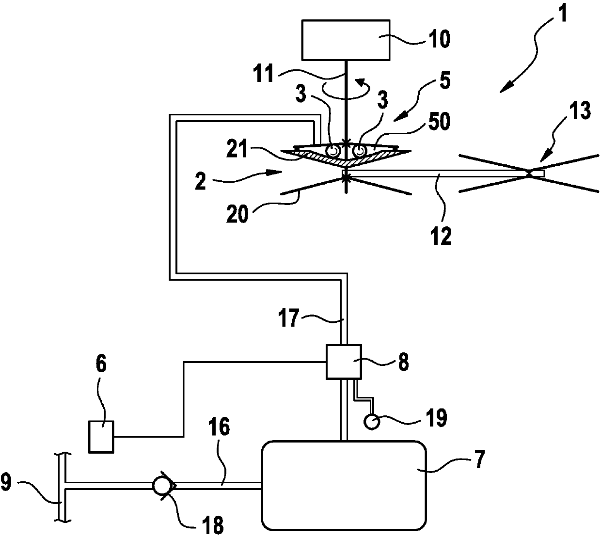
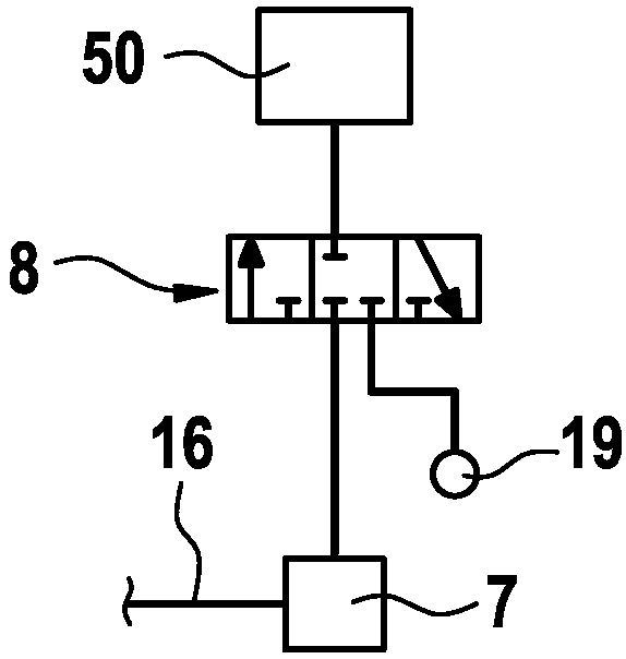
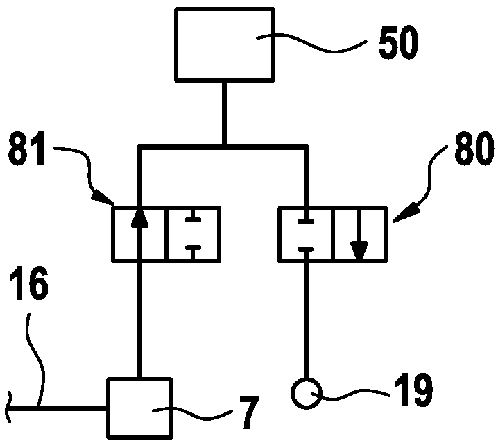
[0022] Refer below Figures 1 to 3 A CVT transmission 1 according to a preferred embodiment of the present invention, that is to say a continuously variable transmission capable of continuous adjustment, is described in detail.

[0023] as by figure 1 It can be seen that the CVT transmission 1 comprises a first cone pair 2 with a fixed cone 20 and an axially movable cone 21 . The second cone pair is provided as driven element 13 . The two cone-disc pairs are connected to one another in a known manner by means of a wrapping means 12 , in particular a belt.

[0024] The first cone pair 2 is arranged on a crankshaft 11 of an internal combustion engine 10 . In this case, the crankshaft 11 is connected to a stationary conical disk 20 .

[0025] The CVT transmission 1 also includes a centrifugal force element 3 which is arranged on an axially movable conical disk 21 . In this embodiment, the centrifugal force element 3 is a ball. Alternatively, solid cylinders or hollow cylind...


PUM


Abstract

The invention relates to a continuously variable transmission (CVT) comprising: a V-pulley (2) that includes at least one axially movable conical disk (21); an adjusting device (5) for adjusting a position of the axially movable conical disk (21); and a control unit (6) designed to actuate the adjusting device (5) in order to change the position of the axially movable conical disk (21). The adjusting device (5) is a pneumatic adjusting device that moves the axially movable conical disk (21) by a pneumatic force.

Description

technical field [0001] The invention relates to a pneumatically adjustable CVT transmission (continuously adjustable transmission), in particular for small vehicles such as two-wheelers, three-wheelers, four-wheelers or snowmobiles, as well as an internal combustion engine and a vehicle. Background technique [0002] CVT transmissions are known in various configurations from the prior art. Due to the continuously variable transmission, in contrast to a transmission with fixed gears, respectively suitable transmission ratios can be achieved in the vehicle. A particular field of application for such CVT transmissions is small vehicles such as two-wheelers, three-wheelers (so-called tucktucks), snowmobiles, four-wheelers or scooters. Centrifugal force adjusters are often used in such CVT transmissions for adjusting the position of the belt on the pair of cones. Here, the centrifugal weight of the centrifugal force regulator shifts its radial position as a function of the rota...

Claims


Application Information

Patent Timeline
IPC IPC(8): F16H9/18F16H63/06F16H55/56
CPCB60Y2400/408F16H9/18F16H55/563F16H61/30F16H63/065
Inventor O·杰伦特I·克勒斯特夫D·施瓦茨I·德鲁R·艾达姆R·狄克曼C·布赖廷格M·克利门科
Owner ROBERT BOSCH GMBH
Learn More