
Prewelding clamping fastening method of exhaust gas purifier for chemical building

A technology for exhaust gas purifiers and buildings, applied in the direction of manufacturing tools, welding equipment, auxiliary welding equipment, etc., can solve the problem of high cost

Inactive Publication Date: 2018-03-27
付云杰
View PDF0 Cites 0 Cited by
  • Summary
  • Abstract
  • Description
  • Claims
  • Application Information

AI Technical Summary

Problems solved by technology

[0003] The invention provides a pre-welding clamping and fastening method for an exhaust gas purifier used in chemical buildings, which solves the problems of high manufacturing cost of traditional purifiers and the like

Method used


Image

  • Prewelding clamping fastening method of exhaust gas purifier for chemical building

Examples


Embodiment 1

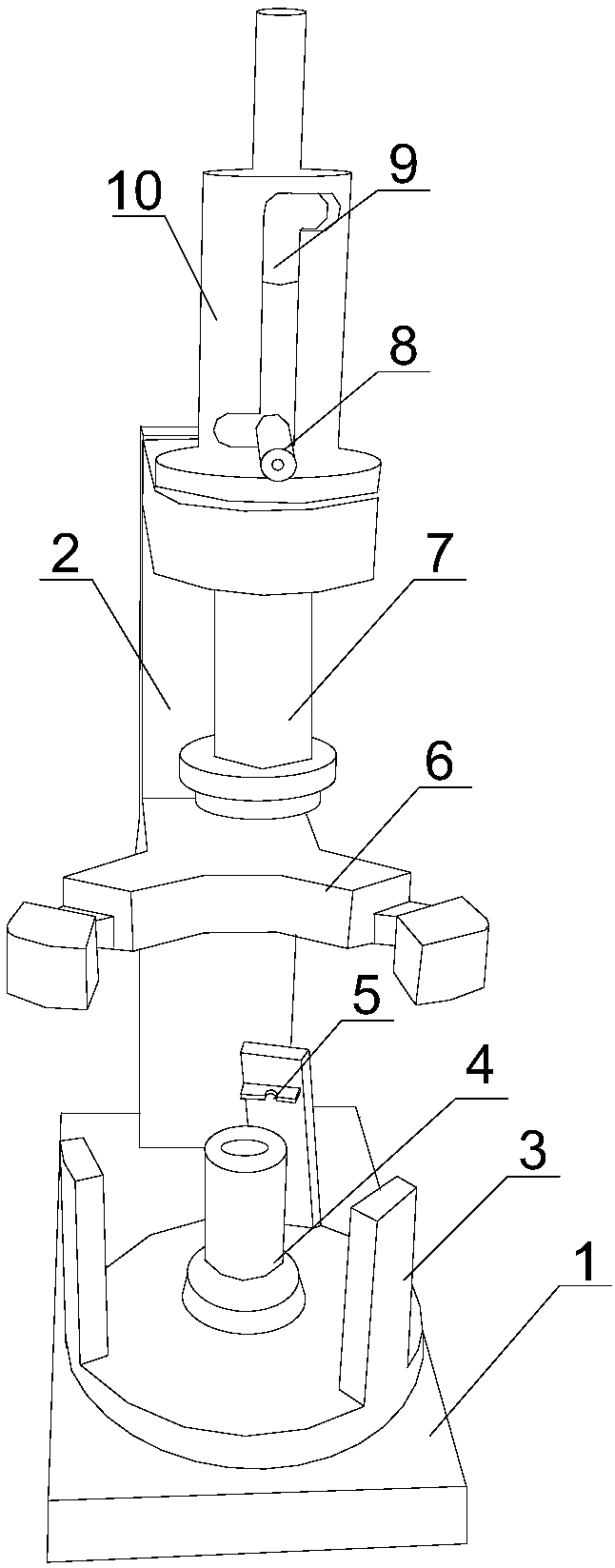
[0013] Such as figure 1 As shown, the pre-welding and clamping and fastening method of the waste gas purifier for chemical buildings of the present invention is realized through the following steps: the clamping process is: first, the semi-finished steel plate that has completed the reel process is manually placed on the clamp, and the The arc-shaped bayonet 6 on the mast 2 is positioned, and finally under the fixing action of the pressing mechanism, welding is started manually to complete the manufacture of the finished purifier shell, wherein the fixture includes a base 1, a mast 2, a support mechanism, an arc Shape bayonet 6, press-down mechanism, described base 1 is vertically connected with mast 2, support mechanism is arranged on the base 1, arc-shaped bayonet 6 is arranged in the middle of mast 2, and the top of mast 2 is provided with press-down mechanism, so The axis lines of the supporting mechanism, the arc bayonet 6 and the pressing mechanism coincide. The semi-fi...

Embodiment 2

[0015] Such as figure 1 As shown, this embodiment is based on Embodiment 1, and the support mechanism includes a support column 4 and a plurality of support plates 3 , and the plurality of support plates 3 are distributed around the support column 4 in a circular array. The function of the support column 4 set in the middle of the support plate 3 is to guide the semi-finished steel plate of the necking to be accurately placed on the welding position, and the surrounding support plate 3 fixes the steel plate itself, so as to avoid the displacement of the semi-finished steel plate when the necking is welded. welding effect.

Embodiment 3

[0017] Such as figure 1 As shown, this embodiment is based on the embodiment 2, and the top of the support plate 3 is also provided with a protrusion 5 . The protrusion 5 at the bottom of the support plate 3 acts as a limiter. During welding, it is inevitable that it will collide with the semi-finished steel plate of the neck. The protrusion 5 can well limit the semi-finished steel plate of the neck between the support plate 3 and the support plate. between the columns 4 to prevent their displacement.


PUM


Abstract

The invention discloses a pre-welding clamping and fastening method for an exhaust gas purifier used in a chemical building, which includes a clamping process. The clamping process is as follows: firstly, the semi-finished steel plate that has completed the rolling process is manually placed on the clamp, and then the steel plate is placed on the mast. The arc-shaped bayonet is positioned, and finally under the fixing action of the pressing mechanism, manual welding is started to complete the manufacture of the finished purifier shell, wherein the fixture includes a base, a mast, a supporting mechanism, an arc-shaped bayonet, a pressing mechanism, the base is vertically connected to the mast, the supporting mechanism is arranged on the base, the arc-shaped bayonet is arranged in the middle of the mast, and the top of the mast is provided with a pressing mechanism, the supporting mechanism, the arc-shaped bayonet and the pressing mechanism Axes coincide. It only needs to place the semi-finished steel plate after the roll in the support mechanism, and it can be welded quickly and effectively.

Description

technical field [0001] The invention relates to the field of sewage purification of chemical buildings, in particular to a pre-welding, clamping and fastening method for waste gas purifiers used in chemical buildings. Background technique [0002] Chemical buildings, especially chemical plants that emit exhaust gas, need to treat the exhaust gas, so an exhaust gas treatment room will be built, and the three-way catalytic converter is a key component installed in the exhaust gas treatment room to purify. It can convert harmful gases such as CO, HC and NOx emitted from exhaust gas into harmless carbon dioxide, water and nitrogen through oxidation and reduction. Because this catalytic converter can convert the main harmful substances in the exhaust gas into harmless substances at the same time. The production of three-way catalytic converters generally goes through processes such as reeling, loading, bundling, necking, and welding. In the production of the cylindrical casing ...

Claims


Application Information

Patent Timeline
IPC IPC(8): B23K37/04
CPCB23K37/04B23K37/0443
Inventor 付云杰
Owner 付云杰
Learn More