
Numerical Calculation Method for Predicting Flue Gas Circulation Sinter-Heat Coupling Process

A flue gas circulation and numerical calculation technology, which is applied in the field of iron ore sintering, can solve the problems that the simulation accuracy of the flue gas circulation process needs to be evaluated, the interaction is taken into account, and the parameter values ​​lack theoretical basis, etc., so as to promote the quality improvement. The effects of increasing production, saving energy and pollution, changing the structure of material layers, and clarifying the physical meaning of parameters

Active Publication Date: 2021-04-20
HUATIAN ENG & TECH CORP MCC +1
View PDF6 Cites 0 Cited by
  • Summary
  • Abstract
  • Description
  • Claims
  • Application Information

AI Technical Summary

Problems solved by technology

However, there are five outstanding problems in the traditional sintering process, including iron ore resources, energy consumption, environmental protection, sintering process control, and waste heat recovery. ” and “hardest hit area”
On October 1, 2012, my country began to implement the "New Standards for the Discharge of Pollutants in the Iron and Steel Industry". As a result, many steel companies' current pollution control and energy-saving measures are difficult to meet the requirements for emission and energy consumption standards. Research and development of new environmentally friendly sintering processes Technology to meet the needs of sustainable development of enterprises has become a consensus
At the same time, the current simulation research has not involved enough flue gas circulation process and the simulation accuracy needs to be evaluated: Publication No. CN105468799A, patent name "Simulation Method for Predicting Thermal State Parameters of High-temperature Waste Gas Circulation Sintering Process" proposes a single-particle microelement However, this method only uses a simple model to solve the three reactions of water migration, limestone decomposition, and fuel combustion, and does not include the circulating flue gas The interaction between the gas phase components that may be triggered by the introduction of the gas phase is taken into account; H.Kang et al. (Proceedings of the Institution of Mechanical Engineers, Part A, 2012) directly adopt the model of W. Yang et al. (ISIJInternational, 2004) Calculation of flue gas circulation process; H.Ahn et al. (Ironmaking and Steelmaking, 2013) developed a two-dimensional mathematical model of flue gas circulation sintering using a commercial process simulator, but did not explain its specific simulation calculation method; Zhang Xiaohui et al. (Central South University Journal of Natural Sciences, 2014) The model also does not consider the possible reactions between the gas phase components of the circulating flue gas
[0005] Through the analysis, it can be seen that the above calculation methods mainly have the following problems: (1) nearly half of the models only consider the heat and mass transfer phenomena in the material layer, but do not consider the change of the material layer structure; (2) most of the models The model only considers the forced convection heat transfer between gas and solid, but basically does not involve the radiation and heat conduction problems; (3) The selection of heat and mass transfer parameters and thermophysical property parameters in the control equation is too empirical and arbitrary ; (4) The reaction mechanism of the physical and chemical process is not revealed enough, and the parameter value lacks a theoretical basis; (5) The description of the interaction between gas phase components is very lacking
Therefore, these models are mostly used for offline operation analysis, and basically do not have the value of industrial application, especially for the flue gas circulation sintering process

Method used


Image

  • Numerical Calculation Method for Predicting Flue Gas Circulation Sinter-Heat Coupling Process
  • Numerical Calculation Method for Predicting Flue Gas Circulation Sinter-Heat Coupling Process
  • Numerical Calculation Method for Predicting Flue Gas Circulation Sinter-Heat Coupling Process

Examples


Embodiment 1

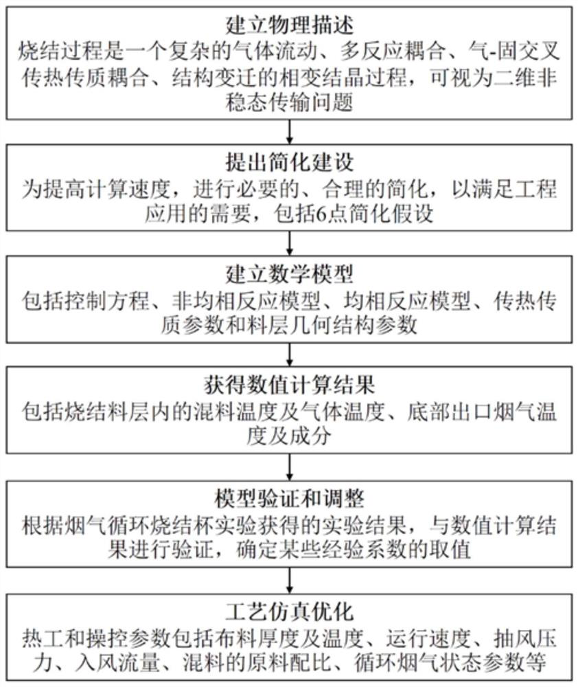
[0249] Example 1, such as figure 1 Shown, the concrete implementation process of the present invention is as follows:

[0250] Step 1, establish a physical description of the traditional sintered mass-thermal coupling process:

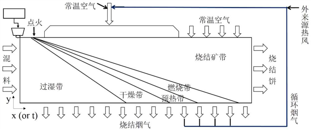
[0251] like figure 2 The schematic diagram of the sintering process of flue gas circulation sintering is shown. According to the temperature and physical and chemical changes, the sintering layer can be divided into sintering zone, combustion zone, preheating zone, drying zone and over-humidity zone from top to bottom. After ignition, five zones appeared one after another, moved downward continuously, and finally all became sinter zones.

[0252] In traditional sintering, room-temperature air is extracted as sintering gas after ignition, while flue gas circulation sintering uses part of the hot flue gas generated by the sintering machine as sintering gas. In this way, the volume of circulating flue gas, the level of temperature, the change of comp...

Embodiment 2

[0338] This implementation provides a numerical calculation method for predicting the mass-thermal coupling process of the flue gas circulation sintering process, at least including establishing a homogeneous reaction model and solving the reaction rate of the homogeneous reaction. The homogeneous reaction model includes CO secondary combustion model, CO 2 Disproportionation reaction model, CH 4Combustion model, H 2 Combustion model, water gas reaction model and CO 2 reduction reaction model,

[0339] Among them, the calculation formula of CO secondary combustion reaction rate is:

[0340]

[0341] CO 2 The calculation formula of disproportionation reaction rate is:

[0342] CH 4 The formula for calculating the combustion reaction rate is:

[0343] h 2 The formula for calculating the combustion reaction rate is:

[0344] The formula for calculating the water gas reaction rate is:

[0345] CO 2 The formula for calculating the reduction reaction rate is: ...

Embodiment 3

[0347] As the specific scheme of embodiment 2, the method also includes the following steps:

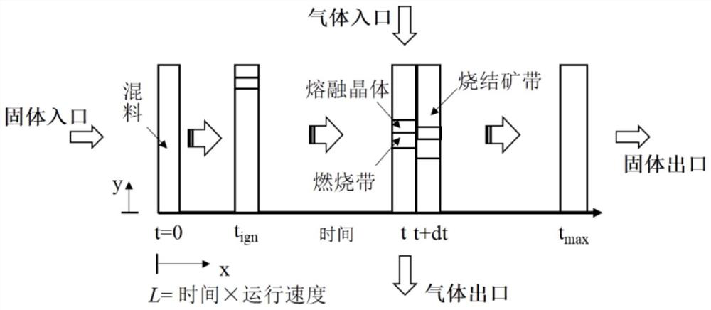
[0348] (1) Establish a mathematical model of the mass-thermal coupling process of the sintering material layer in the sintering machine, the mathematical model is a two-dimensional unsteady model, which is used to describe the flow of cross heat exchange between the sintering material layer and the gas in the sintering machine, Heat transfer combustion and chemical reaction, that is, the sintering process is simplified to a two-dimensional transport process in the thickness direction of the material layer and the running direction of the sintering machine, and a heterogeneous reaction model is established at the same time; wherein, the two-dimensional unsteady sintered mass - The governing equations for the mathematical model of the thermally coupled process include:

[0349] (1.1) Gas mass conservation equation:

[0350] (1.2) Mixed mass conservation equation:

[0351] (1.3) G...


PUM

PropertyMeasurementUnit
porosityaaaaaaaaaa
porosityaaaaaaaaaa

Abstract

The invention discloses a numerical calculation method for predicting the thermal coupling process of flue gas circulation sintered mass, which comprises the following steps: (1) establishing a two-dimensional unsteady-state mathematical model of the thermal coupling process of the sintered material layer in the sintering machine; (2) ) According to the homogeneous reaction model and the heterogeneous reaction model, solve the thermal effect of each substance in the sintering process, and then solve the mass source item and heat source item in the mathematical model control equation; (3) According to the heat and mass transfer parameters, material layer geometry Calculate the convection and diffusion terms in the control equation for structural parameters; (4) calculate the mixture temperature and gas temperature in the sintered material layer, the flue gas temperature and composition at the bottom outlet; (5) calculate the obtained in step (4) The results are compared and verified with the actual results to determine the value of the empirical coefficient; (6) optimization simulation is carried out, and the thermal parameters and control parameters in the actual production are simulated and analyzed to optimize the flue gas circulation sintering process.

Description

technical field [0001] The invention relates to the technical field of iron ore sintering, in particular to a calculation method for predicting flue gas circulation sintered mass-thermal coupling process. Background technique [0002] Sintering is currently one of the most important agglomeration technologies for the production of man-made iron-rich ores. The world's first belt sintering machine was put into operation in the United States in 1910. In the past 30 years, domestic and foreign sintering technologies have made great progress around optimizing sintering ore blending, process and equipment, which has gradually improved the technical indicators of sintering ore. However, there are five outstanding problems in the traditional sintering process, including iron ore resources, energy consumption, environmental protection, sintering process control, and waste heat recovery. " and "hardest hit area". On October 1, 2012, my country began to implement the "New Standards ...

Claims


Application Information

Patent Timeline
Patent Type & Authority Patents(China)
IPC IPC(8): G16C20/10
CPCG16C20/10
Inventor 王淦王浩余波
Owner HUATIAN ENG & TECH CORP MCC
Learn More