High-precision automatic filling device
An automatic filling and high-precision technology, which is applied in the direction of packaging, transportation and packaging, and the type of packaged items. It can solve the problems of mixing, low equipment life, easy delivery, etc., and achieve good technical effects, high efficiency, low cost, and good structure. simple effect
- Summary
- Abstract
- Description
- Claims
- Application Information
AI Technical Summary
Problems solved by technology
Method used
Image
Examples
Embodiment 1
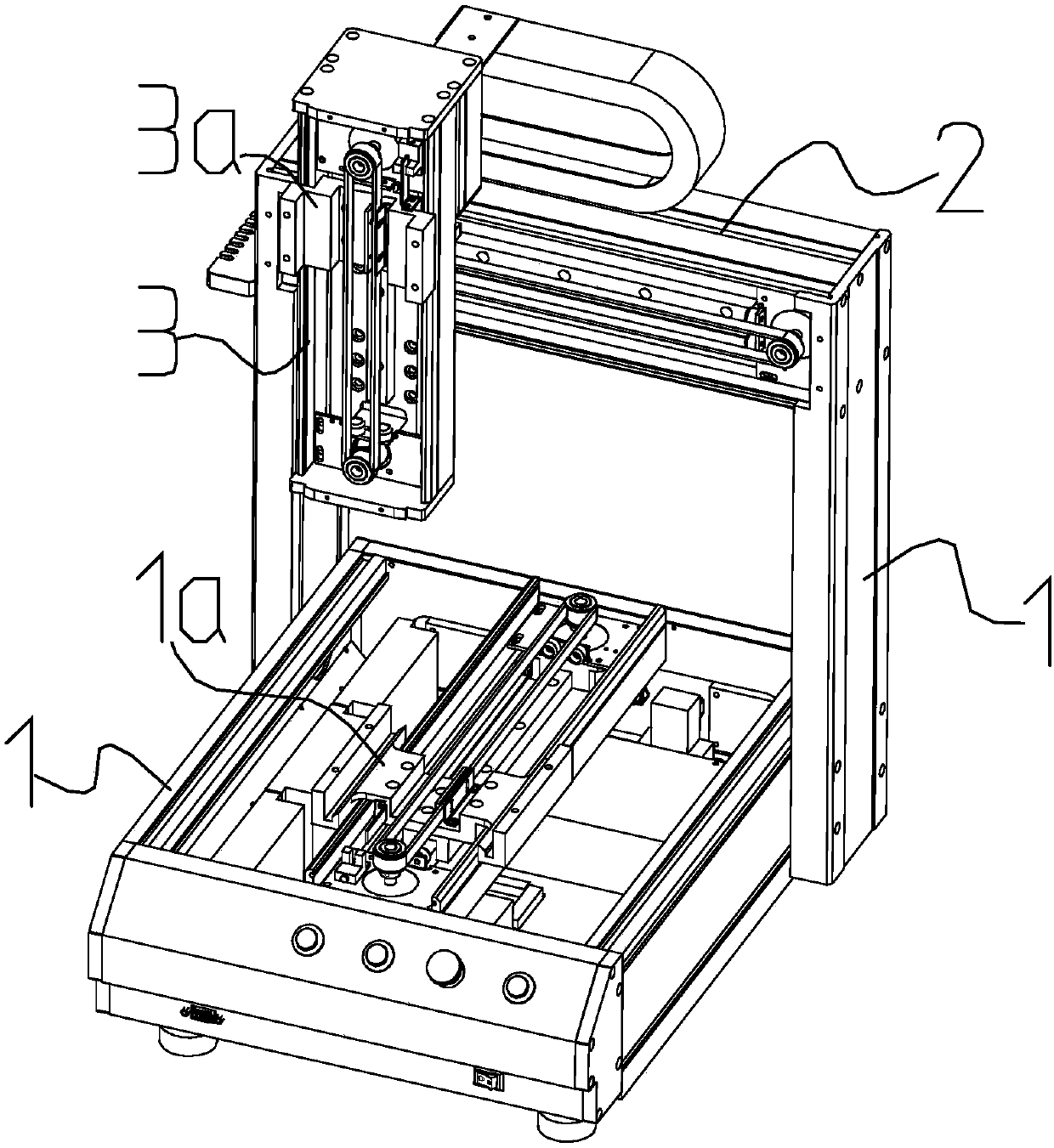
[0020] Example 1, such as figure 1 As shown, the overall composition of the present invention is to provide a high-precision automatic filling device, which includes a horizontal sliding housing 1, a lateral supporting housing 2 and a vertical supporting housing 3, and the horizontal sliding housing is a horizontal Rectangular shell, with a panel on the horizontal sliding shell, equipped with a sliding tray that can slide back and forth along the longitudinal rail along the longitudinal guide rail, the sliding tray protrudes out of the panel, and the horizontal support The two ends of the shell are respectively fixed to both sides of the horizontal sliding shell through a supporting wall, so that the horizontal supporting shell is arranged above the horizontal sliding shell, and longitudinal guide rails are erected in the horizontal sliding shell, and the horizontal sliding shell There is a linear drive unit in the body, the linear drive unit is set in parallel with the longit...
Embodiment 2
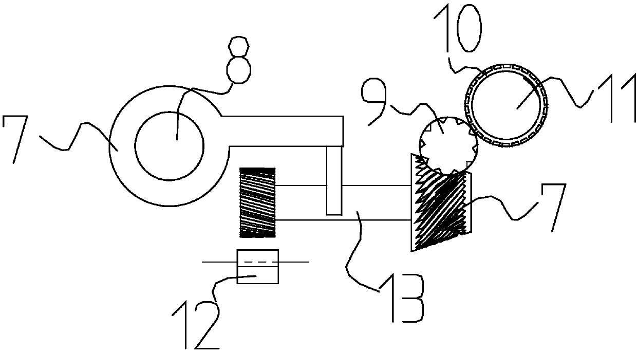
[0022] Embodiment 2 includes the content of above-mentioned embodiment 1, and each described linear drive unit all comprises power screw shaft 8, transition feed shaft 13, transition shaft 9, precision screw shaft 11 and shell, has power screw shaft on the shell. The shaft through hole, the transition shaft through hole and the precision screw shaft through hole, the power screw shaft, the transition shaft and the precision screw shaft are parallel to each other, and a shaft seat is provided at each end of the power screw shaft, and a shaft seat is provided in the shell. The moving limit assembly is used to guide and limit the driving slider 7. The moving limiting component is a structure in which the connecting frame and the guide rail are arranged on the inner wall of the housing. The driving slider 7 is a screw sleeve, and an extension is provided on the driving slider. Out of the plate, there is a clamp opening on the protruding plate, and the transition feed shaft is fitte...
Embodiment 3
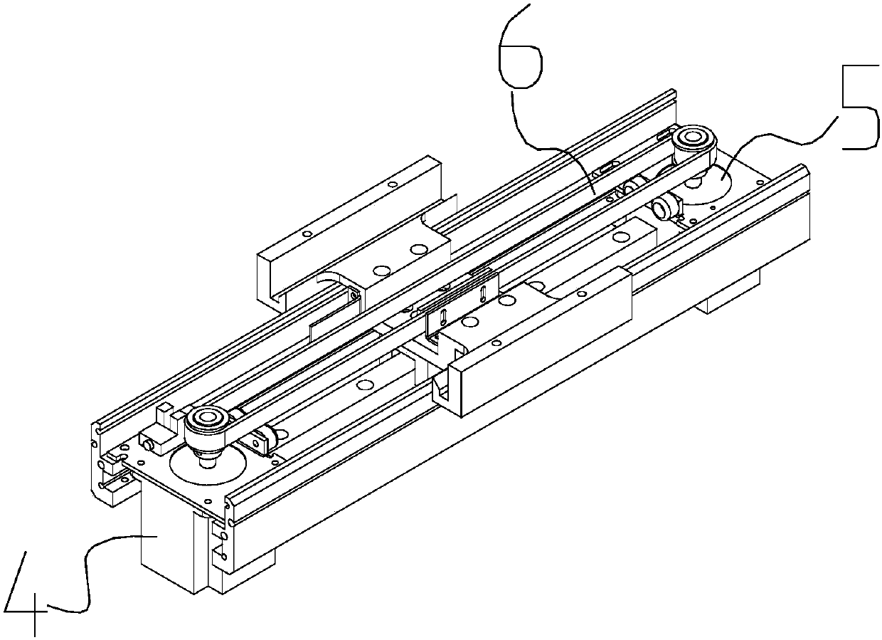
[0026] Embodiment 3, including the difference between Embodiment 1 and Embodiment 1, is that the linear drive unit includes a first drive motor 4 and a second drive motor 5, between the drive shafts of the first drive motor and the second drive motor A conveyor belt 6 is installed between them, and the conveyor belt of the linear drive unit inside the horizontal sliding housing 1, the horizontal supporting housing 2, and the vertical supporting housing 3 corresponds to the sliding tray, the horizontal sliding block, and the vertical sliding block one by one. Fixed connection.
PUM
 Abstract
Description
Claims
Application Information
 - R&D
- Intellectual Property
- Life Sciences
- Materials
- Tech Scout
- Unparalleled Data Quality
- Higher Quality Content
- 60% Fewer Hallucinations
Browse by: Latest US Patents, China's latest patents, Technical Efficacy Thesaurus, Application Domain, Technology Topic, Popular Technical Reports.
© 2025 PatSnap. All rights reserved.Legal|Privacy policy|Modern Slavery Act Transparency Statement|Sitemap|About US| Contact US: help@patsnap.com


