
Single-pixel camera system based on multi-mode optical fiber

A multi-mode optical fiber and single-pixel technology, which is applied in the field of single-pixel camera systems, can solve the problems of high lens requirements, increased device complexity, and high price, and achieve the effects of simplifying experimental devices, avoiding diffraction limit, and strong scalability

Active Publication Date: 2018-03-20
HARBIN INST OF TECH SHENZHEN GRADUATE SCHOOL
View PDF3 Cites 15 Cited by
  • Summary
  • Abstract
  • Description
  • Claims
  • Application Information

AI Technical Summary

Problems solved by technology

[0005] For the traditional single-pixel camera model, the structured light is collected and transmitted through the lens, especially in the optical circuit from the DMD to the detector. Due to the aberration and spherical aberration of the traditional lens, coupled with the interference of the surrounding environment noise, the The image quality of the later stage has a great impact
Not only that, because the photosensitive area of ​​the unit detector is very small, we need to determine the position of the lens according to the size of the object plane and the size ratio of the photosensitive surface, which leads to higher requirements for the lens and cannot guarantee the collected light. All of them enter the photosensitive surface, resulting in the loss of part of the light intensity information, which directly leads to a decrease in the signal-to-noise ratio of the device. Of course, it is possible to purchase some sophisticated optical mobile platforms to solve the problem of collecting all the reflected light into the photosensitive surface. First, it will Increase the complexity of the device, second, it will increase the cost of the experiment, the price is relatively expensive

Method used


Image

  • Single-pixel camera system based on multi-mode optical fiber
  • Single-pixel camera system based on multi-mode optical fiber
  • Single-pixel camera system based on multi-mode optical fiber

Examples


Embodiment Construction

[0017] The present invention will be further described below in conjunction with the accompanying drawings.

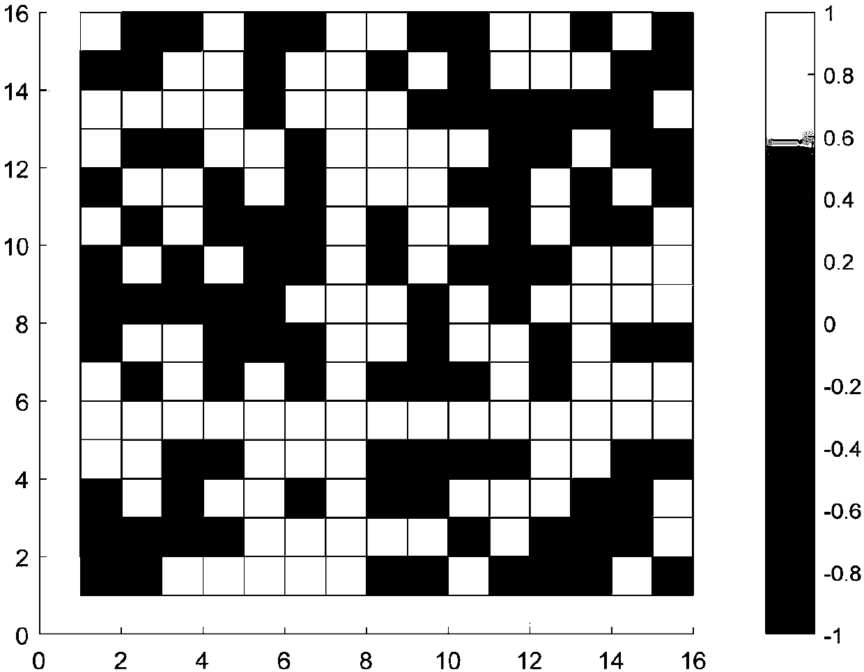
[0018] as attached figure 1 As shown, first generate a Hadamard matrix with a size of N×N, and then randomly select M row vectors from the Hadamard matrix, and the partial Hadamard matrix obtained after selecting M rows has strong non-correlation characteristics and Partially orthogonal, so the measurement matrix requires fewer observations than other matrices, but due to the construction of the Hadamard matrix itself, its dimension must be an integer power of 2.

[0019] Walsh transform has the following characteristics: fast algorithm, real number operation, addition and subtraction, fast speed, can be realized by hardware, and low precision.

[0020] Rademaker function:

[0021] R(n,t)=sign[sin(2 n πt)] (1)

[0022] Walsh functions for Walsh sequences:

[0023]

[0024] p=log 2 (N) is the number of bits corresponding to the sequence, is the Gray code; the...


PUM


Abstract

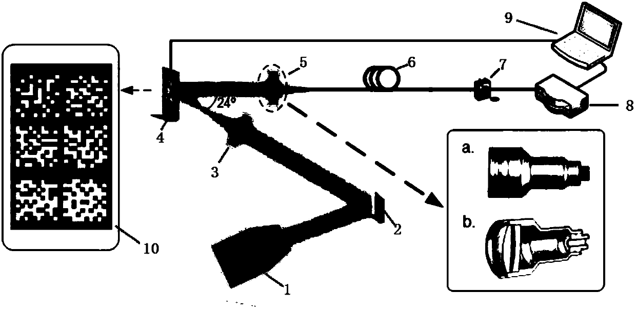
The invention provides a single-pixel camera system based on a multi-mode optical fiber, which has the advantages of high signal-to-noise ratio, simple optical path structure and high expansibility. The single-pixel camera system mainly comprises a DMD modulation portion, a data acquisition portion and an algorithm recovery portion. Specifically, the traditional single-pixel camera system converges light modulated by a DMD to a light sensitive surface of a unit detector by using a lens, then the light is converted into a corresponding light intensity value through A / D conversion, and imaging can be performed by inputting the light intensity value into a recovery algorithm by combining an observation matrix. The method utilizing the general lens often brings great noise interference to an experiment result, and the signal-to-noise ratio of the system is reduced by influences of the aberration generated by convergence of the lens for the space light, the dispersion of light and the ambient light in the light propagation process in addition to system noise and environmental noise. The utilization of the multi-mode optical fiber on the basis not only can reduce the loss of light transmission in the space, but also can realize single-pixel imaging in a specific band. Only an optical fiber with a specific transmission wavelength is required to be replaced.

Description

technical field [0001] The invention belongs to the field of optical imaging systems and image processing, in particular to a single-pixel camera system. Background technique [0002] With the rapid development of science and technology today, while the amount of information and data that people need to obtain is increasing exponentially, it also poses great challenges to traditional data acquisition technologies. In terms of imaging technology, such as MRI and digital cameras, the COMOS array sensor on the digital camera collects a large amount of data, and then compresses and discards 90% of the data. In the process of collection, a large amount of data is collected only for subsequent deletion, so why not discard a large proportion of redundant information at the beginning, only collect a small part of data, and decompress a large amount of original data from these small amounts of data? relevant information. [0003] In 2006, a new type of original signal or image was ...

Claims


Application Information

Patent Timeline
IPC IPC(8): G03B17/02
CPCG03B17/02
Inventor 肖君军吴波吴绍华张田田刘承徽罗斌
Owner HARBIN INST OF TECH SHENZHEN GRADUATE SCHOOL
Learn More