
Drying and pelletizing device for chemical engineering

A drying system and chemical technology, applied in the field of chemical drying and granulation equipment, can solve the problems of uneven heating, low drying efficiency, waste of energy, etc., to increase the heat exchange surface area, increase the contact area, increase The effect of heat transfer efficiency

Inactive Publication Date: 2018-03-20
四川旭瑞达机电设备有限公司
View PDF6 Cites 3 Cited by
  • Summary
  • Abstract
  • Description
  • Claims
  • Application Information

AI Technical Summary

Problems solved by technology

[0002] In the process of chemical production, a large number of heating, drying and granulation devices are needed. The existing technology is not systematic, the production continuity is not strong, and the production efficiency is low. In addition, in the prior art granulation process, the screen is easy to block , the sieving efficiency is not high, and there is a large dust pollution, causing certain harm to the staff
In the existing material drying equipment, its main body is usually a box structure, with an inlet at one end and an outlet at the other end, and a drying channel between the inlet and the outlet. Wheel transmission mechanism and heater, use the heater to heat the drying belt, and use the belt wheel transmission mechanism to transfer the material to the drying channel, so as to achieve the purpose of heating and drying the material, although this method can dry the material However, in order to ensure the drying effect of the material, the thickness of the material to be dried each time should not be too thick, and the drying efficiency is low; and to ensure a good drying effect on the basis of high drying efficiency, the thickness of the dried material cannot be made Afterwards, therefore, it is necessary to increase the power of the heater and speed up the transmission efficiency of the pulley transmission mechanism. This method also has the defects of wasting energy, time and labor, and the material may also be heated unevenly, and the drying effect of the material is not good. First, even some materials undergo qualitative changes at excessively high temperatures

Method used


Image

  • Drying and pelletizing device for chemical engineering
  • Drying and pelletizing device for chemical engineering

Examples


Embodiment Construction

[0019] The present invention will be further described below with reference to the accompanying drawings and embodiments, and the mode of the present invention includes but not limited to the following embodiments.

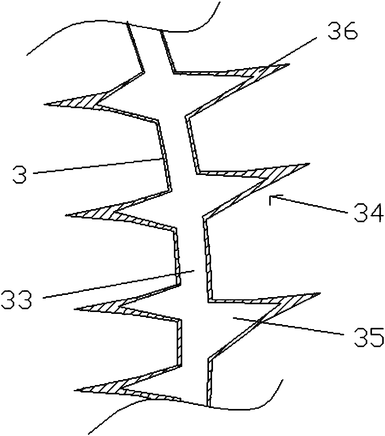
[0020] The purpose of this embodiment is to provide a material drying device with simple structure, reasonable design, good drying effect and high drying efficiency, such as figure 1 As shown, the drying device mainly includes two support bases 1, a drum 2, a steam coil 3, a motor 4 and a material classification device.

[0021] Specifically, two ends of the drum 2 are fixedly provided with a connecting end 21, and the two connecting ends are respectively connected to the two supporting bases 1 through rotating bearings; the steam coil 3 is a spiral steam coil, The steam coil is close to the inner wall of the drum and is spirally arranged along the axis of the drum. The two ends of the steam coil 3 are respectively connected with a steam inlet pipe 31 and a steam ...


PUM


Abstract

The invention discloses a drying and pelletizing device for chemical engineering. The drying and pelletizing device comprises two supporting bases, a rotary barrel, a steam pipe coil and a motor; thetwo ends of the rotary barrel are each provided with a connecting end, and the rotary barrel are rotationally connected with the two supporting bases through the two connecting ends; the steam pipe coil is tightly attached to the inner wall of the rotary barrel and is arranged in the axis direction of the rotary barrel spirally, and the two ends of the steam pipe coil are communicated with a steam inlet pipe and a steam outlet pipe corresponding; a plurality of fins are arranged on the steam pipe coil in the spiral direction, the roots of the fins are internally provided with fin cavities communicated with hollow runners, and the ends of the fins are fin blades with the isosceles triangle cross sections; the rotary barrel is provided with a material inlet and a material outlet; and the output end of the motor is connected with the connecting end of a chain, and the rotary barrel is further driven to rotate. The drying device is simple in structure, reasonable in design, even in material heating, and capable of conducting cutting and pelletizing while drying operation is carried out; and the equipment is high in systematicness, good in drying effect and high in production efficiency.

Description

technical field [0001] The invention relates to a chemical drying and granulating device. Background technique [0002] In the process of chemical production, a large number of heating, drying and granulation devices are needed. The existing technology is not systematic, the production continuity is not strong, and the production efficiency is low. In addition, in the prior art granulation process, the screen is easy to block , the sieving efficiency is not high, and there is a large dust pollution, which will cause certain harm to the staff. In the existing material drying equipment, its main body is usually a box structure, with an inlet at one end and an outlet at the other end, and a drying channel between the inlet and the outlet. Wheel transmission mechanism and heater, use the heater to heat the drying belt, and use the belt wheel transmission mechanism to transfer the material to the drying channel, so as to achieve the purpose of heating and drying the material, al...

Claims


Application Information

Patent Timeline
Patent Type & Authority Applications(China)
IPC IPC(8): F26B11/06F26B23/10F26B25/00F26B25/02F26B25/04B01J2/12B07B1/34B07B1/42
CPCB01J2/12F26B11/0468F26B23/10F26B25/002F26B25/02F26B25/04B07B1/34B07B1/42
Inventor 王馨淳
Owner 四川旭瑞达机电设备有限公司
Learn More