
Rapid and high-precision correction method for beam path of electron accelerator

An electron accelerator and high-precision technology, applied in the direction of instruments, adaptive control, control/adjustment systems, etc., can solve problems such as difficulty, and achieve safety, high practical applicability and reliability, accuracy and speed sexual effect

Inactive Publication Date: 2018-03-16
郭鑫
View PDF0 Cites 1 Cited by
  • Summary
  • Abstract
  • Description
  • Claims
  • Application Information

AI Technical Summary

Problems solved by technology

The principle of this calibration work is not very complicated, but it is not easy to make correct movements in a short period of time. It often takes several years of work accumulation to become familiar with this adjustment process

Method used


Image

  • Rapid and high-precision correction method for beam path of electron accelerator
  • Rapid and high-precision correction method for beam path of electron accelerator
  • Rapid and high-precision correction method for beam path of electron accelerator

Examples


Embodiment Construction

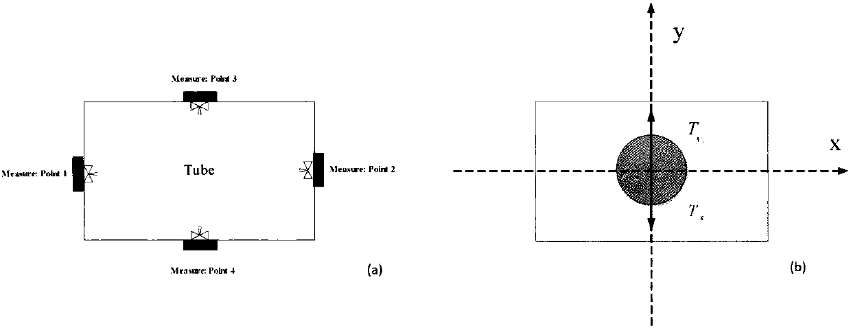
[0011] The present invention designs a detection method based on dual sensor information fusion, which is used to quickly prepare and detect the beam path. The schematic diagram of the structure layout is as follows figure 1 shown. Install a beam probe on the inner wall of the beam pipe to detect the beam intensity at the four walls of the beam pipe, and install a high-precision digital temperature sensor on the outer wall of the beam pipe to detect the temperature of the four walls of the beam pipe. The real-time displacement of the beam is obtained by the average weighting algorithm.

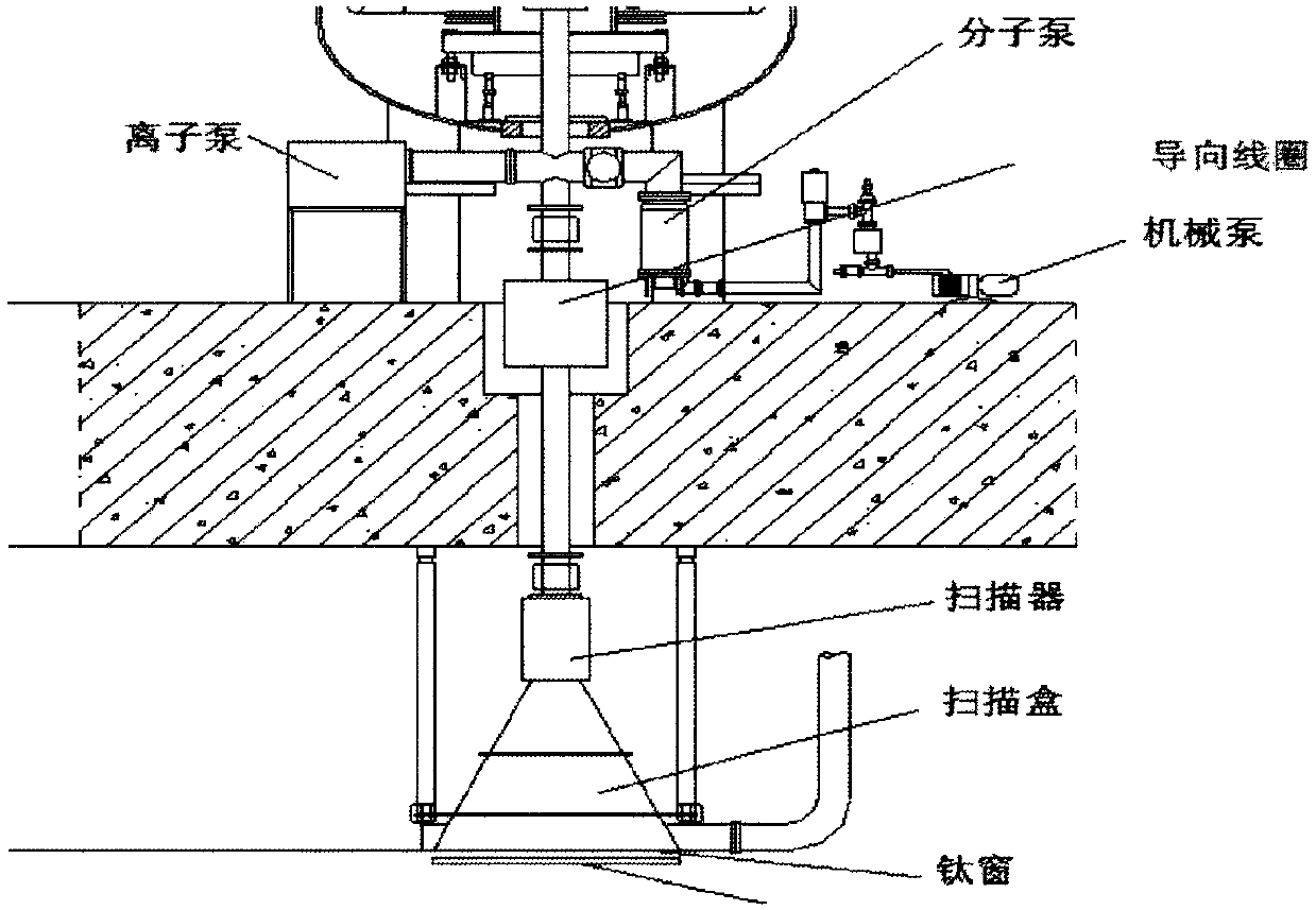
[0012] The structure diagram of the non-contact electron beam current control system designed by the present invention is as follows: figure 2 As shown, the guide coil is installed outside the beam pipe, and the special triangular wave excitation power supplies power to the scanning magnet. By controlling the alternating current of the two-dimensional steering coil, the magnetic field gener...


PUM


Abstract

Aiming at the current situation that there is no substantial progress in the current electron accelerator beam control strategy, the present invention designs an automatic correction system for the electron accelerator beam path, which is fast and high-precision through a beam displacement detection technology based on a dual-sensor information coupling algorithm. The beam path is detected and the non-contact high-precision beam control is used to realize the automatic adjustment of the beam path based on the cerebellar model neural network PID control, which further simplifies the difficulty of manual operation and makes the operation of the accelerator easier and safer. Through experiments and debugging, the beam current control method of the electron accelerator has been optimized, which can meet the control requirements of the accelerator with higher performance.

Description

technical field [0001] The invention belongs to the field of accelerator beam current control, and in particular relates to a method for quickly correcting the beam current path of an electron accelerator. Background technique [0002] Electron accelerators are widely used in the irradiation processing of products, and are a common source of irradiation in industrial and agricultural production processes. In the field of electron accelerator control, looking at the products of several domestic accelerator manufacturers, some improvements have been made in improving the control level of the control system. However, for beam control, one of the main control strategies, there are still no breakthrough research results. [0003] During the beam training process of the electron accelerator, it is necessary to comprehensively judge and adjust multiple parameters to ensure normal beam output. Once the accelerator system sparks or some uncertain abnormal conditions cause the devia...

Claims


Application Information

Patent Timeline
IPC IPC(8): G05B13/04
CPCG05B13/04
Inventor 郭鑫
Owner 郭鑫
Learn More