
Unstable flow guiding device for pump

A diversion device and a technology for stabilizing flow, which is applied to parts, pumps, and pump components of elastic fluid pumping devices, can solve problems such as unit vibration, flow head curve hump, noise, etc., and reduce unit vibration, The flow state is stable and the effect of improving flow efficiency

Inactive Publication Date: 2018-03-16
JIANGSU UNIV
View PDF5 Cites 0 Cited by
  • Summary
  • Abstract
  • Description
  • Claims
  • Application Information

AI Technical Summary

Problems solved by technology

However, the patent does not involve how to solve the backflow at the leading edge of the pump inlet and the device for improving the flow state of the pump inlet
[0006] Generally speaking, when the pump is operating in a non-design working condition, the fluid flow in the pump is unstable, often accompanied by unstable phenomena such as backflow and vortex, which have a great impact on the main flow. The form acts on the flow-passing parts such as the impeller, which will cause the pump to run unstable, and also cause vibration and noise of the unit. In addition, the unstable flow will make the flow head curve of the pump hump, which will affect the normal operation of the pump. In addition, the change of pump flow conditions may also cause pump cavitation, and the occurrence of cavitation will also cause vibration and noise of the unit, seriously affecting the operation stability of the unit and the economic loss of users
The existing method to improve the return flow at the pump inlet is generally to add an inducer before the impeller, but sometimes it is not possible to obtain a reasonable flow head curve only by rationally selecting the geometric parameters of the flow-passing parts such as the inducer.

Method used


Image

  • Unstable flow guiding device for pump
  • Unstable flow guiding device for pump
  • Unstable flow guiding device for pump

Examples


Embodiment Construction

[0027] The present invention will be further described below in conjunction with the accompanying drawings and specific embodiments, but the protection scope of the present invention is not limited thereto.

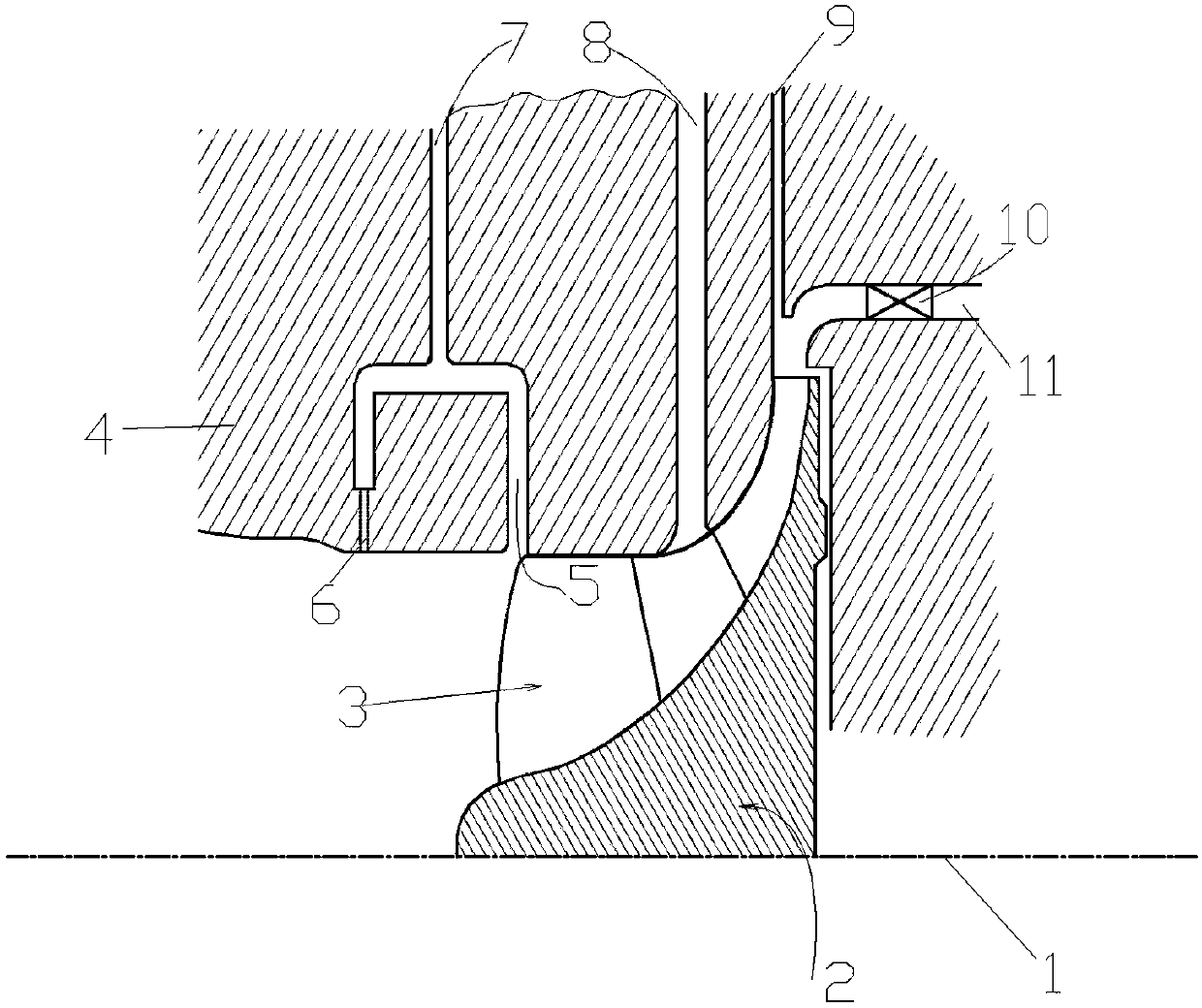
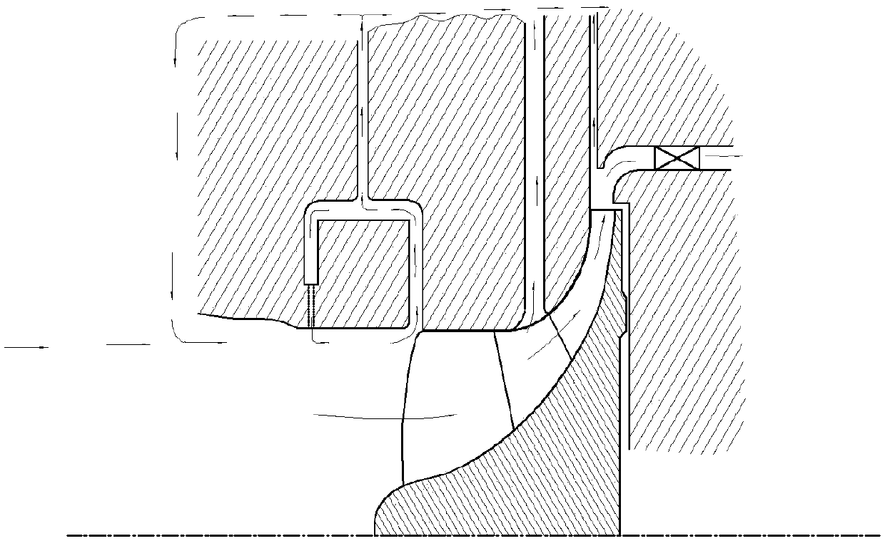
[0028] Such as figure 1 As shown, a kind of unsteady flow guide device for pumps, including some inlet guide grooves 5, some middle guide grooves 8 and some outlet guide grooves 9; the area between the casing 4 and the impeller body 2 is set In the wheel channel 3, any one of the inlet guide grooves 5 is in the housing 4, and the inlet guide groove 5 includes a main pipe 7 and a front return pipe 6; the main pipe 7 is located at the inlet edge of the impeller flow channel 3 The pump cavity is connected with the impeller channel 3 through the inlet diversion groove 5; one end of the front-end return pipe 6 is connected with the main pipe 7, and the other end of the front-end return pipe 6 is connected with the pump chamber; any of the middle guides The flow groove 8 is in...


PUM


Abstract

The invention provides an unstable flow guiding device for a pump. The unstable flow guiding device for the pump comprises a plurality of inlet flow guiding grooves, a plurality of middle flow guidinggrooves and a plurality of outlet flow guiding grooves; an area between a shell and an impeller body is arranged into an impeller flow channel; the inlet flow guiding grooves each comprise a main pipeline and a front end backflow pipeline; each main pipeline is located at the position of the edge of an inlet of the impeller flow channel; one end of each front end backflow pipeline is connected with the main pipeline; the other end of the front end backflow pipeline is communicated with a pump cavity; any middle flow guiding groove is in the shell, and is located on the middle portion of the impeller flow channel; an outlet flow guiding groove is in the shell, and is located at the outlet position of the impeller flow channel; and the inlet flow guiding grooves, the middle flow guiding grooves and the outlet flow guiding grooves are uniformly distributed in the radial direction of the center line of the axis. By means of the unstable flow guiding device for the pump, influences of existence of blades on main flow can be reduced, the phenomena of backflow, vortexes and the like generated at different positions in the flowing process can be effectively improved, and the flowing efficiency is greatly improved.

Description

technical field [0001] The invention relates to the field of impeller pumps, in particular to an unstable flow guide device for pumps. Background technique [0002] When the pump is running in a non-design working condition, the flow of the fluid is very unstable, and the phenomenon of backflow and vortex before the inlet of the impeller / inducer has a particularly obvious impact on the mainstream. Generally, an inducer is installed in front of the impeller to improve Improve the flow performance of the pump, improve the flow stability of the pump and the safe and reliable operation of the unit. However, sometimes it is not possible to obtain a reliable flow-head curve only by rationally selecting the geometric parameters of the inducer and other flow-passing parts. Therefore, reasonable structural measures are needed to effectively solve the phenomenon of backflow and vortex at the leading edge of the pump inlet. [0003] In addition, when the pump inlet pressure drops to a...

Claims


Application Information

Patent Timeline
Patent Type & Authority Applications(China)
IPC IPC(8): F04D29/40F04D29/66
CPCF04D29/406F04D29/669
Inventor 付强康俊鋆朱荣生王秀礼刘刚钟伟源李梦圆
Owner JIANGSU UNIV
Learn More