Joint structure of multi-coupled steel component
A technology for node structure and steel components, which is applied in building structures, buildings, etc., can solve the problems of low strength at the connection between high-strength steel components and steel castings, low strength of cast steel parts, and long processing cycles, and achieve weight reduction. , shorten the processing cycle, improve the effect of local stiffness
- Summary
- Abstract
- Description
- Claims
- Application Information
AI Technical Summary
Problems solved by technology
Method used
Image

Examples
Embodiment 1
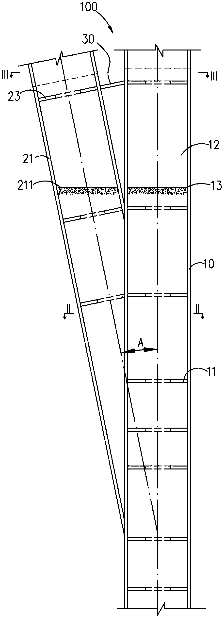
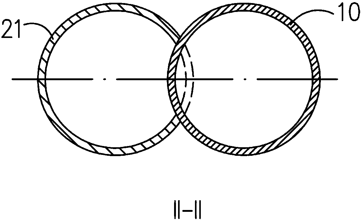
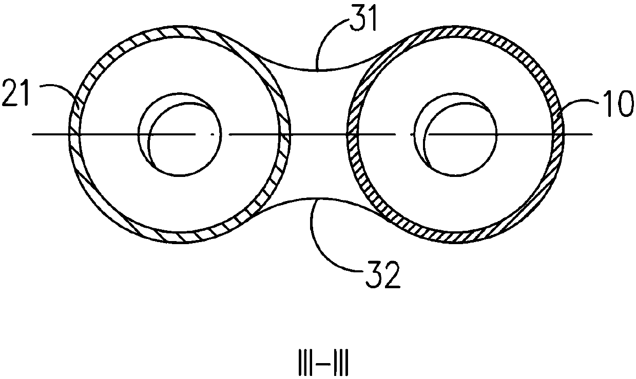
[0055] Please also see figure 1 , figure 2 , image 3 as well as Figure 5 , is a structural schematic diagram of the node structure of the multi-joint steel member provided by the embodiment of the present invention. The node structure 100 of the multi-joint steel member provided by the embodiment of the present invention includes a main member 10 and several connecting members 20, the main member 10 is a hollow tubular structure, and the connecting node area 11 is arranged on the main member 10, the main member 10 A plurality of first inner reinforcing ring plates 12 are provided corresponding to the connection node area 11 , and each first inner reinforcing ring plate 12 is arranged at intervals along the height direction of the main member 10 . The plurality of connecting members 20 are fixedly connected to the main member 10 , and one end of the plurality of connecting members 20 fixedly connected to the main member 10 is located in the connection node area 11 .
[0...
Embodiment 2
[0085] Please also refer to Figure 6 and Figure 7 , is a schematic diagram of the node structure of the multi-joint steel member provided by Embodiment 2 of the present invention. The difference between the joint structure 200 of the multi-joint steel member provided by the second embodiment of the present invention and the joint structure 100 of the multi-joint steel member provided by the first embodiment of the present invention is that:
[0086] In this embodiment, the main component 10 is provided with a node area steel pipe 201 corresponding to the connection node area 11, and the node area steel tube 201 is connected to the inner wall of the main component 10, and the wall thickness of the node area steel tube 201 is greater than that of the main component 10. wall thickness. Specifically, since the connection node region 11 is an important stress-bearing region, the wall thickness of the steel pipe 201 in the node region should be greater than that of the main memb...
Embodiment 3
[0092] Please also refer to Figure 8 to Figure 11 , is a schematic diagram of the node structure 200 of the multi-joint steel member provided by Embodiment 3 of the present invention. The difference between the joint structure 300 of the multi-joint steel member provided by the third embodiment of the present invention and the joint structure 100 of the multi-joint steel member of the first embodiment of the present invention is that:
[0093] The main component 10 includes a first part 301 and a second part 302, the first part 301 is a straight pipe arranged vertically, the second part 302 is an oblique pipe arranged obliquely relative to the vertical center of the first part 301, the second part 302 is connected with the top end of the first part 301 to form a first inclined angle C. That is to say, the main component 10 is a partially inclined pipe, and in order to ensure the stress and facilitate the force analysis, the first angle C of inclination should not be too larg...
PUM
 Abstract
Description
Claims
Application Information
 - R&D
- Intellectual Property
- Life Sciences
- Materials
- Tech Scout
- Unparalleled Data Quality
- Higher Quality Content
- 60% Fewer Hallucinations
Browse by: Latest US Patents, China's latest patents, Technical Efficacy Thesaurus, Application Domain, Technology Topic, Popular Technical Reports.
© 2025 PatSnap. All rights reserved.Legal|Privacy policy|Modern Slavery Act Transparency Statement|Sitemap|About US| Contact US: help@patsnap.com