
Device for testing voltage resistance of plug

A technology of withstand voltage detection and detection device, which is applied in the direction of using liquid/vacuum for liquid tightness measurement, etc., can solve problems such as the decline of insulation performance, reduce the sealing area, save time and economic cost, and reduce the axial direction. The effect of thrust

Pending Publication Date: 2018-03-13
北京环鼎科技有限责任公司
View PDF0 Cites 1 Cited by
  • Summary
  • Abstract
  • Description
  • Claims
  • Application Information

AI Technical Summary

Problems solved by technology

[0006] The present invention aims to overcome the problem that the insulation performance of the 18-core high-voltage plug in the prior art is greatly reduced during the experiment and affects normal use, and provides a plug withstand voltage detection device, which can effectively avoid the detection of the insulation of the 18-core high-voltage plug. Sexual impact, so that it can be used normally after being tested

Method used


Image

  • Device for testing voltage resistance of plug
  • Device for testing voltage resistance of plug
  • Device for testing voltage resistance of plug

Examples


Embodiment 1

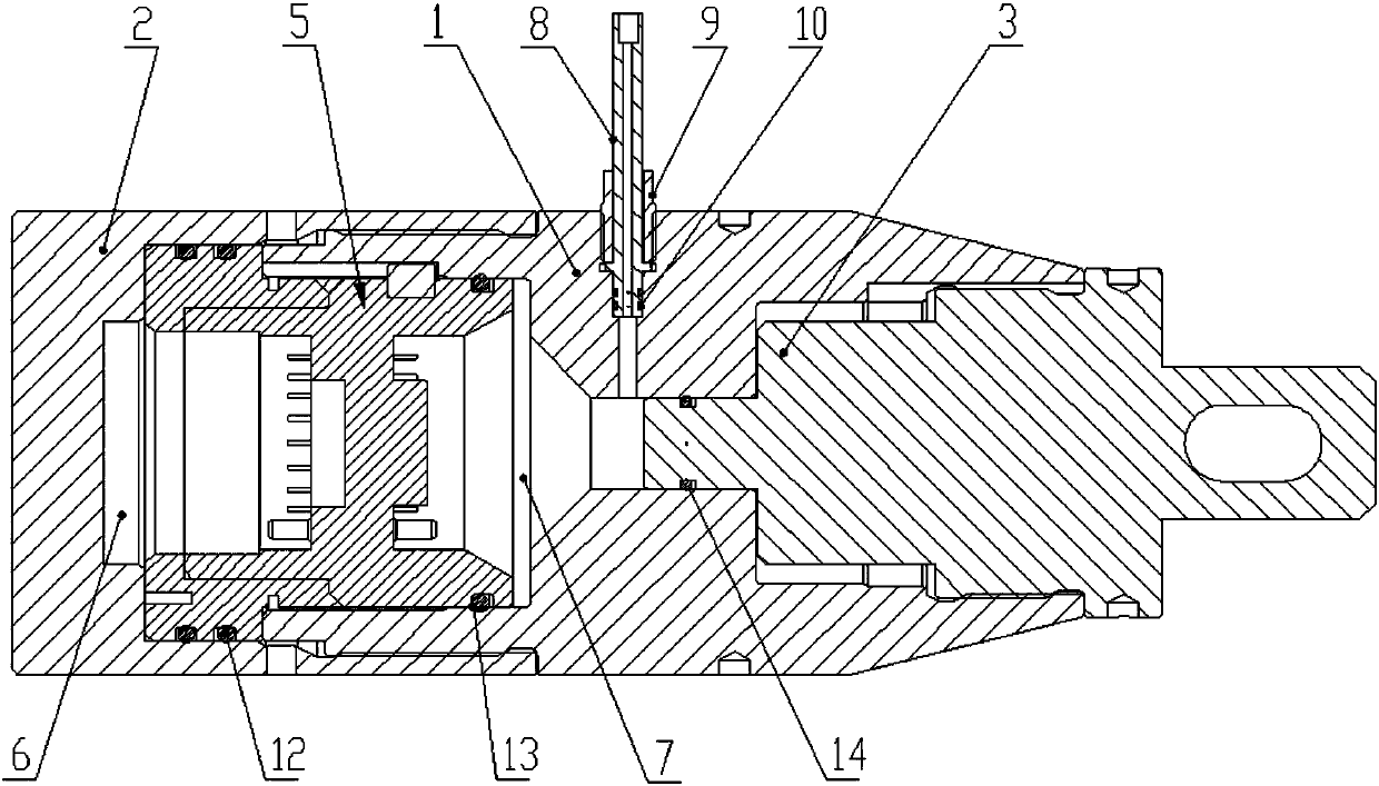
[0033] Such as figure 1 As shown, the present invention provides a plug pressure testing device, including a main body 1, a sealing outer casing 2, a sealing plug 3 and a pressurizing device. One end of the main body 1 is connected to the sealing outer casing 2 through threads, and the other end is connected to the sealing plug 3 connection, the joint between the sealing plug 3 and the main body 1 is installed with a plug sealing ring 14 for sealing, the sealing plug 3 is a stepped structure, and the outer diameter of the sealing surface is smaller than the outer diameter of the sealing plug 3; the main body 1 and the sealing A cavity for placing the detection plug 5 is formed between the jackets 2. The detection plug 5 divides the cavity into two parts: a low-pressure chamber 6 and a high-pressure chamber 7. A high-pressure chamber for sealing the detection plug 5 and the main body 1 is installed in the high-pressure chamber 7 A sealing ring 13, a low-pressure chamber sealin...

Embodiment 2

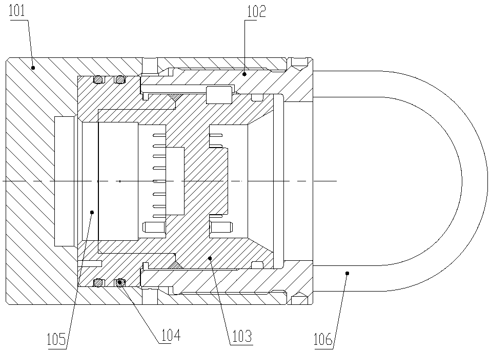
[0041] Such as figure 2 As stated above, the present invention replaces the sealing plug 3 in Embodiment 1 with a balance piston assembly 4, and the balance piston assembly 4 includes a balancing piston 42 located in the housing 41 and inside the housing 41 for the balance piston 42 to move along the radial direction of the balance piston assembly 41. Chamber 43, balance piston 42 connected with balance chamber 43 through spring 44, and the rest are the same as in embodiment 1.

[0042] The invention provides a plug withstand voltage detection device in a high-temperature and high-pressure well to conduct experiments at 140MPa and 175°C, including the following steps:

[0043] S5: Replace the sealing plug 3 with the balance piston assembly 4;

[0044] S6: Vacuumize the high-pressure chamber 7, inject silicone oil from the high-pressure oil pipe 8 into the high-pressure chamber 7 through the oil injection pump, and push the balance piston 42 to the rightmost side of the balance...


PUM


Abstract

The invention discloses a device for testing voltage resistance of a plug. The device comprises a body (1), a sealing sleeve (2), a sealing plug (3), a balance piston assembly (4) and a voltage applying device. One end of the body (1) is connected with the sealing sleeve (2), and the other end is connected with the sealing plug (3) or the balance piston assembly (4). A chamber for placing a testing plug (5) is formed between the body (1) and the sealing sleeve (2). The testing plug (5) divides the chamber to a low-pressure chamber (6) and a high-pressure chamber (7). The voltage applying device is fixedly mounted outside the body (1). The sealing plug (3) and the balance piston assembly (4) have the same screw specification and the same sealing surface dimension, and can be freely switched. The device can effectively prevent influence of a detecting process to insulating property of the testing plug (5) so that normal use of the testing plug (5) is not affected after testing and furthermore can realize free switching between normal-temperature preliminary testing and high-temperature high-voltage testing of the plug.

Description

technical field [0001] The invention relates to a detection device, in particular to a pressure-resistant detection device used for detection of high-voltage plugs in the field of petroleum well logging. Background technique [0002] In the field of petroleum logging, petroleum logging instruments are in a high-temperature and high-pressure environment downhole, and the electronic components in the instrument are usually in a closed low-pressure chamber because they cannot withstand high pressure, and the pressure in the chamber is close to that of ordinary Atmospheric pressure. Outside the low-pressure chamber, the pressure on other parts of the instrument is the same as the actual pressure of the formation, up to 140MPa, which is called the high-pressure area. [0003] In order to realize the connection of electronic components or circuits in the high-voltage area with the circuits in the low-voltage chamber, high-voltage plugs are required. The high-voltage plug can wit...

Claims


Application Information

Patent Timeline
Patent Type & Authority Applications(China)
IPC IPC(8): G01M3/02
CPCG01M3/02
Inventor 郭宝左李英波刘金柱高秦群
Owner 北京环鼎科技有限责任公司
Learn More