
Hand vacuum cleaner with cyclone

A cyclone separator and vacuum cleaner technology, which is applied in the direction of vacuum cleaners, suction filters, cleaning equipment, etc., can solve the problems of local bulkiness, and achieve the effect of low cost, simple and compact structure, and compactness and realization

Inactive Publication Date: 2018-03-13
GENIUS GMBH
View PDF10 Cites 7 Cited by
  • Summary
  • Abstract
  • Description
  • Claims
  • Application Information

AI Technical Summary

Problems solved by technology

[0005] The hand-held vacuum cleaners known from the prior art are disadvantageously constructed in parts very heavy and / or can only be held with great effort when cleaning walls or ceilings with one hand

Method used


Image

  • Hand vacuum cleaner with cyclone
  • Hand vacuum cleaner with cyclone
  • Hand vacuum cleaner with cyclone

Examples


Embodiment Construction

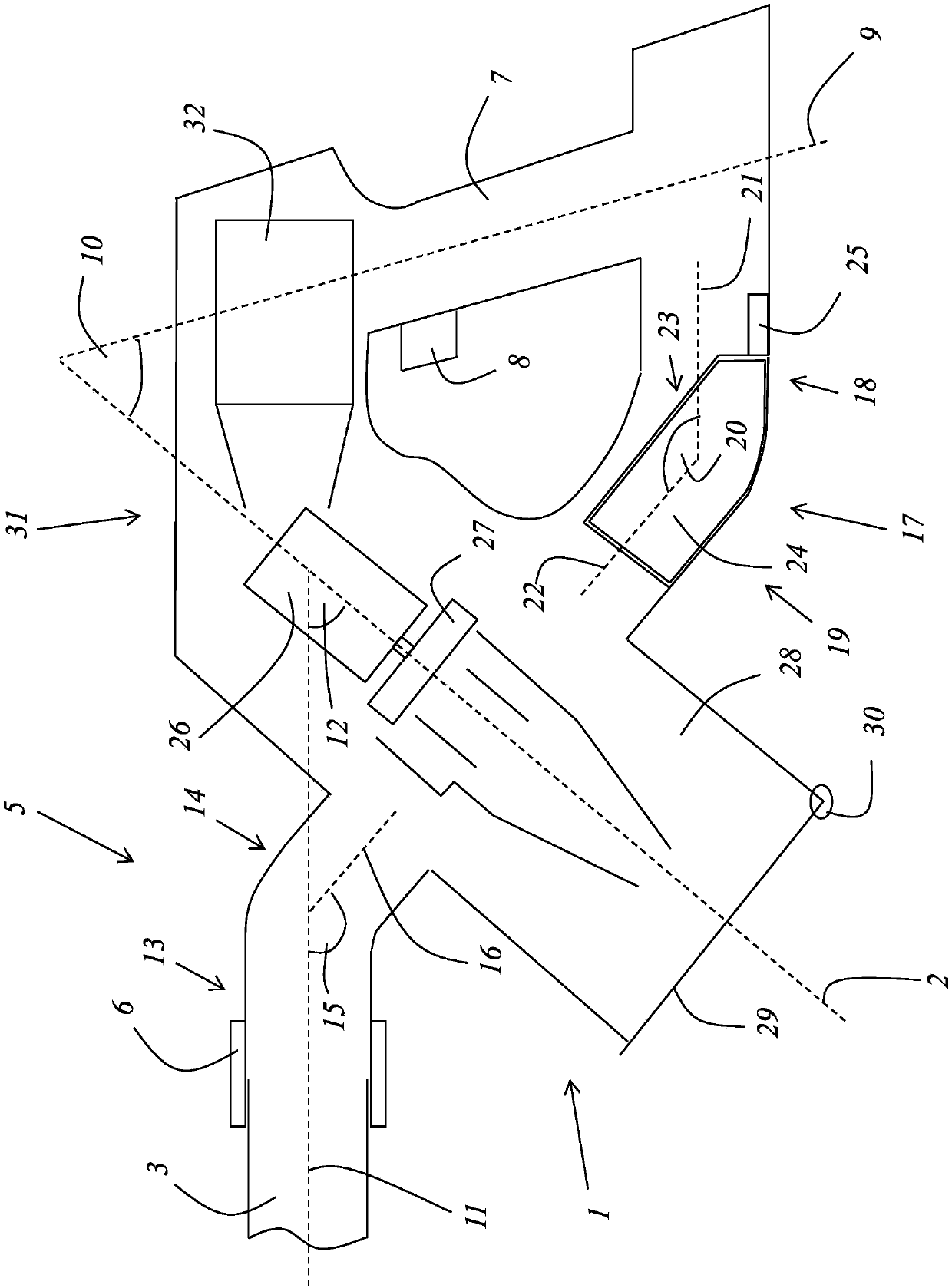
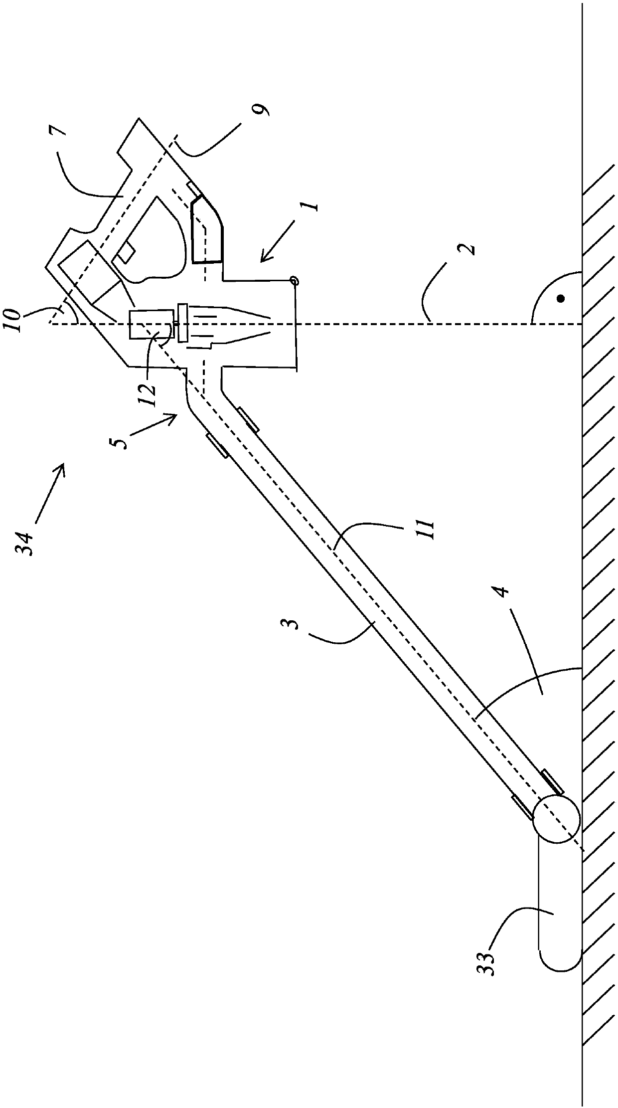
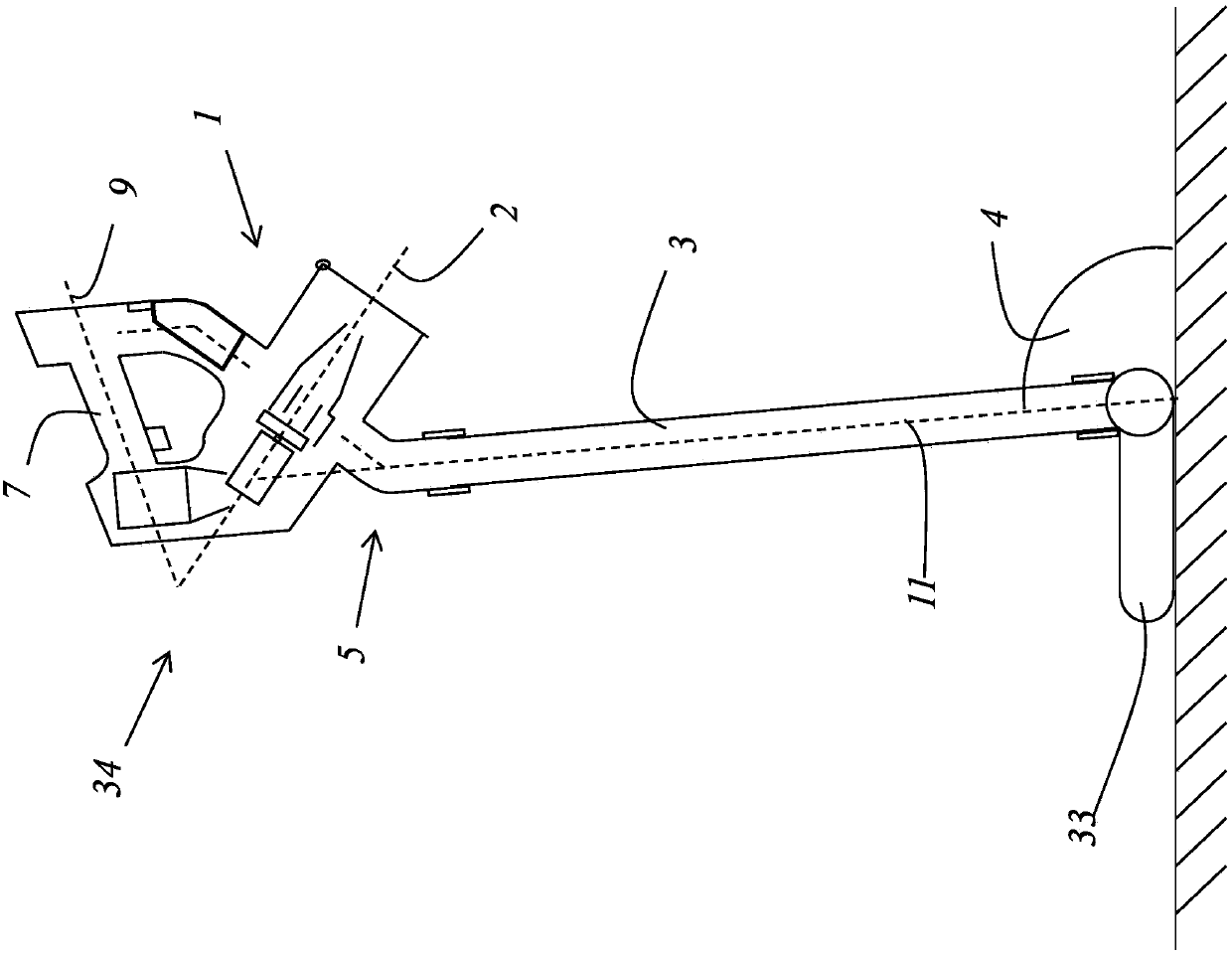
[0041] figure 1 It is a detailed view of an embodiment of the hand-held vacuum cleaner of the present invention, which has a cyclone separator 1 . In this cyclone separator 1 , the air to be cleaned rotates about an axis of rotation 2 .

[0042] The hand-held vacuum cleaner also has an elongated suction pipe 3 which is connected at one end to an angled connection piece 5 which connects the suction pipe 3 to the cyclone separator 1 . In order to connect the suction line 3 in particular without tools, a stop device 6 is provided on the connecting piece 5 . in the suction line ( figure 1 (not shown) the other end can be connected to a suction nozzle. The hand-held vacuum cleaner has a pistol-grip handle 7 . An on-button 8 is arranged on the handle 7 , which the user can actuate with his forefinger when he has gripped the handle 7 . In particular, the switch-on button 8 can be designed as a regulator with which the user can select the suction power. It can advantageously be ...


PUM


Abstract

The invention relates to a hand vacuum cleaner, it has cyclone and the long and thin suction tube and the handle of pistol handle formula, treats that clear air is rotatory around rotation axis in cyclone, and the one end of suction tube is used for connecting suction nozzle by the design. This hand vacuum cleaner's characterized in that, rotation axis presss from both sides the first angle into being greater than 30 degrees with the longitudinal extension axis of handle each other. Replacing ground or can advantageously stipulating with attaching, rotation axis presss from both sides the second angle into being less than 90 degrees (right angles) with the longitudinal extension axis of suction tube each other.

Description

technical field [0001] The invention relates to a hand-held vacuum cleaner with a cyclone separator in which the air to be cleaned rotates around an axis of rotation and an elongated suction pipe and a pistol-grip handle, the suction One end of the tube is designed to be attached to a suction nozzle. Background technique [0002] From EP 2 043 493 B1 a hand-held vacuum cleaner is known which has a main body, a dirty air inlet, a clean air outlet and a cyclone-separating device for separating dirt from the air flow, wherein the cyclone-separating The device is arranged in a substantially vertical orientation, wherein the base of the main body and the base of the cyclone-separating device jointly form the base of the device for supporting the device on a surface, wherein the base of the main body is substantially is planar, the base of the cyclone separator is likewise substantially planar, wherein the base of the body lies in the plane of the base of the cyclone separator. ...

Claims


Application Information

Patent Timeline
Patent Type & Authority Applications(China)
IPC IPC(8): A47L5/24A47L9/16
CPCA47L5/24A47L9/16A47L9/248
Inventor 切多米尔·雷帕茨
Owner GENIUS GMBH
Learn More