Compressed sensing imaging device and method
An imaging device and compressive sensing technology, which can be used in measurement devices, re-radiation of electromagnetic waves, utilization of re-radiation, etc., and can solve problems such as poor applicability and low accuracy of target images.
- Summary
- Abstract
- Description
- Claims
- Application Information
AI Technical Summary
Problems solved by technology
Method used
Image

Examples
Embodiment 2
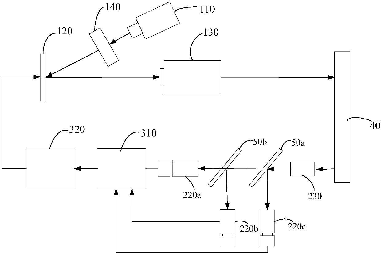
[0049] The difference from Embodiment 1 is that in this embodiment, the multi-channel detection system 20 includes a light receiving unit 230 for collecting the reflected beam of the detection target, a beam splitting unit connected to the light receiving unit, and a A plurality of photodetectors 220 corresponding to the beam splitting unit, each photodetector 220 detects light of one wavelength in the non-monochromatic light source, the beam splitting unit divides the reflected light beam into lights of different wavelengths, through The photodetector 220 corresponding to the wavelength detects. Specifically, the light receiving unit 230 is used to collect the multi-wavelength light beams reflected by the detection target 40 and transmit them to the beam splitting unit. One or more light receiving units 230 can be provided in one-to-one correspondence with the photodetectors 220. In the embodiment, a light receiving unit 230 is provided, and the light receiving unit 230 is lo...
Embodiment 3
[0051]Different from Embodiment 1, in this embodiment, the non-monochromatic light source 110 includes a light source array composed of several monochromatic light sources with different wavelengths. In this embodiment, three monochromatic light sources are taken as an example, which are red light source 111a, green light source 111b, and blue light source 111c. The three light sources can be arranged in dislocations, and the light emitted is independent of each other. They can also be fused by setting optical elements. a beam such as Figure 4 As shown, by arranging the third mirror 50c and the fourth mirror 50d, the beams emitted by the three light sources are merged into one beam, and the third mirror 50c is selected as a mirror that transmits red light and reflects green light , the fourth transflector 50d is selected as the transmissive mirror for red light and green light and blue light reflection, the red light source 111a, the third transflector 50c and the fourth tran...
Embodiment 4
[0054] Such as Figure 5 As shown, the difference from Embodiment 3 is that in this embodiment, the multi-channel detection system 20 includes a light receiving unit 230 for collecting the reflected light beam of the detection target, and a beam splitter connected to the light receiving unit. Unit and several photodetectors 220 corresponding to the beam splitting unit, each photodetector 220 detects light of one wavelength in the non-monochromatic light source, and the beam splitting unit divides the reflected light beam into different wavelengths The light is detected by the photodetector 220 corresponding to the wavelength. Specifically, the light receiving unit 230 is used to collect the multi-wavelength light beams reflected by the detection target 40 and transmit them to the beam splitting unit. One or more light receiving units 230 can be provided in one-to-one correspondence with the photodetectors 220. In the embodiment, a light receiving unit 230 is provided, and the...
PUM
 Abstract
Description
Claims
Application Information
 - R&D
- Intellectual Property
- Life Sciences
- Materials
- Tech Scout
- Unparalleled Data Quality
- Higher Quality Content
- 60% Fewer Hallucinations
Browse by: Latest US Patents, China's latest patents, Technical Efficacy Thesaurus, Application Domain, Technology Topic, Popular Technical Reports.
© 2025 PatSnap. All rights reserved.Legal|Privacy policy|Modern Slavery Act Transparency Statement|Sitemap|About US| Contact US: help@patsnap.com