Sealing property detection device with four-station loading rotary table

A four-station technology for tightness detection, which is applied in the direction of using liquid/vacuum degree for liquid tightness measurement and measuring the acceleration and deceleration rate of fluid, etc. order and other problems to achieve the effect of reducing equipment footprint, speeding up feeding efficiency, and improving detection efficiency

Pending Publication Date: 2018-03-09
SUZHOU RS TECH
View PDF0 Cites 6 Cited by
  • Summary
  • Abstract
  • Description
  • Claims
  • Application Information

AI Technical Summary

Problems solved by technology

[0002] On some products with cavities or through holes, parts need to be installed in the cavities or through holes. In order to form a seal between the parts and the base, a sealing layer is often set between the two For sealing, in order to test the tightness after the combination of the two, the method of pressing down on one side of the cavity or hole is usually used to seal the hole on the part and pump it on the other side of the cavity or hole. Negative pressure is used to test the tightness. In the traditional testing device, the pressure of the downward pressure will make the gap between the component and the base smaller, and the smaller gap will improve the sealing performance of the two parts. However, this will lead to missed detection of products with poor sealing performance, greatly reducing the detection success rate and detection accuracy; The circulation efficiency is low, which greatly reduces the processing efficiency of parts; thirdly, the existing airtightness detection device has a low degree of automation, requires many steps of manual assistance, and cannot be accurately and orderly among multiple detection mechanisms , rhythmically loading and unloading products or efficient sorting of detected products, resulting in low detection efficiency

Method used


Image

  • Sealing property detection device with four-station loading rotary table
  • Sealing property detection device with four-station loading rotary table
  • Sealing property detection device with four-station loading rotary table

Examples


Embodiment Construction

[0059] The present invention will be further described in detail below in conjunction with the accompanying drawings, and the aforementioned and other objects, features, aspects and advantages of the present invention will become more apparent, so that those skilled in the art can implement them with reference to the description. In the drawings, the shapes and dimensions may be exaggerated for clarity, and the same reference numerals will be used throughout to designate the same or like parts. In the following description, terms such as center, thickness, height, length, front, back, rear, left, right, top, bottom, upper, lower, etc. are based on the orientation or positional relationship shown in the drawings. In particular, "height" corresponds to the dimension from top to bottom, "width" corresponds to the dimension from left to right, and "depth" corresponds to the dimension from front to back. These relative terms are for convenience of description and are generally not ...


PUM


Abstract

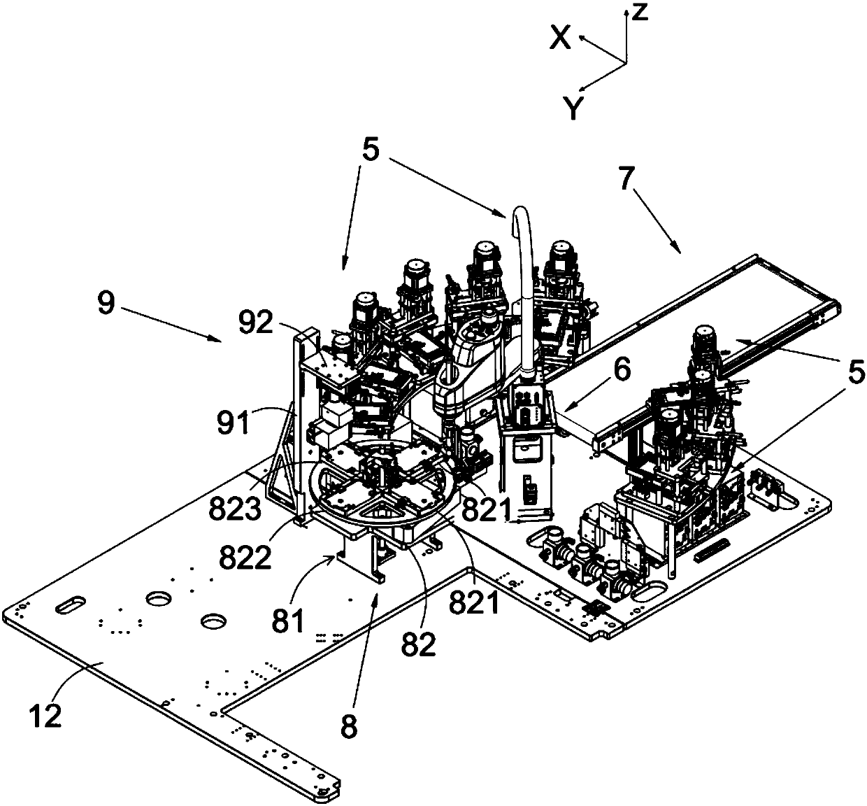
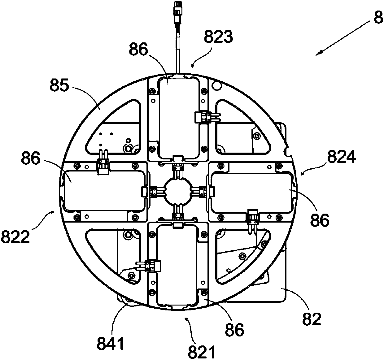
The invention discloses a sealing property detection device with a four-station loading rotary table. The sealing property detection device comprises a mounting-dismounting mechanical arm, the four-station loading rotary table and multiple groups of detection mechanisms, wherein the four-station loading rotary table and the detection mechanisms are arranged beside the mounting-dismounting mechanical arm; the mounting-dismounting mechanical arm can rotate around an axis Z, and the four-station loading rotary table and the detection mechanisms are distributed on a rotation track of the mounting-dismounting mechanical arm in a surrounding manner. According to the sealing property detection device, after a to-be-detected part is subjected to film lamination and is closed, a to-be-detected product is pressed downwards so as to seal a cavity or a through hole from top to bottom, is aerated or exhausted and is then subjected to the sealing property detection, so that the precision of the sealing property detection is increased, meanwhile, the success rate of the sealing property detection can be increased, and a missing detection or false detection phenomenon is avoided; and besides, a linear loading transfer manner is replaced with a rotary loading transfer manner, so that the loading transfer efficiency is greatly improved, the occupied space of equipment is reduced, and the detection efficiency is greatly improved.

Description

technical field [0001] The invention relates to the field of leak detection, in particular to a leak detection device with a four-station feeding turntable. Background technique [0002] On some products with cavities or through holes, parts need to be installed in the cavities or through holes. In order to form a seal between the parts and the base, a sealing layer is often set between the two For sealing, in order to test the tightness after the combination of the two, the method of pressing down on one side of the cavity or hole is usually used to seal the hole on the part and pump it on the other side of the cavity or hole. Negative pressure is used to test the tightness. In the traditional testing device, the pressure of the downward pressure will make the gap between the component and the base smaller, and the smaller gap will improve the sealing performance of the two parts. However, this will lead to missed detection of products with poor sealing performance, greatl...

Claims


Application Information

Patent Timeline
IPC IPC(8): G01M3/26
CPCG01M3/26
Inventor 吴加富缪磊陈冉马伟黎宗彩
Owner SUZHOU RS TECH
Why Eureka
Try Eureka