
Rebar scanning device

A technology for scanning devices and steel bars, which is applied in measuring devices, instruments, surveying and navigation, etc. It can solve the problems of no indication function of steel bar scanners, affect the working efficiency of scanners, and prone to sore joints, etc., and achieve high reliability, Effects of improving safety and improving user comfort

Inactive Publication Date: 2018-03-09
王伟
View PDF5 Cites 2 Cited by
  • Summary
  • Abstract
  • Description
  • Claims
  • Application Information

AI Technical Summary

Problems solved by technology

[0003] In the prior art, the existing steel bar scanner does not have the function of indicating. When the staff scans the position of the steel bar with the steel bar scanner, they can only mark the approximate position of the steel bar with the naked eye. Errors are prone to occur when marking, which affects the The working efficiency of the scanner, the existing steel bar scanner does not have the function of massage, when the staff scans for a long time, the joints such as fingers and arms are prone to sore symptoms, which causes the staff to work in a fatigued state, the existing backpack function Relatively single, now there is an urgent need for a steel bar scanning device to solve the above-mentioned problems

Method used


Image

  • Rebar scanning device
  • Rebar scanning device
  • Rebar scanning device

Examples


specific Embodiment approach

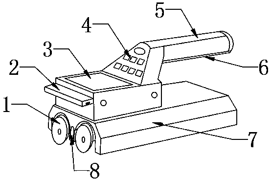
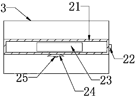
[0026] Specific implementation method: when the steel bar scanner is scanning, the staff needs to mark the position of the steel bar after scanning. At this time, the staff turns on the indicator switch 22, and the indicator switch 22 is switched to the on state, and the battery sheet 23 transmits the electric energy through the wire In the infrared lamp 25, the infrared lamp 25 irradiates the light-on state in the lamp groove 24, because the infrared lamp 25 and the scanning probe 8 are perpendicular to the same horizontal plane, so the position illuminated by the infrared lamp 25 is the position scanned by the scanning probe 8. The position of the steel bar can be marked by the staff according to the position irradiated by the infrared lamp 25, which facilitates the staff to accurately mark the position of the steel bar, reduces errors, and improves the functionality of the present invention.

[0027] When the staff is using the steel bar scanner to work, the staff holds the ...


PUM


Abstract

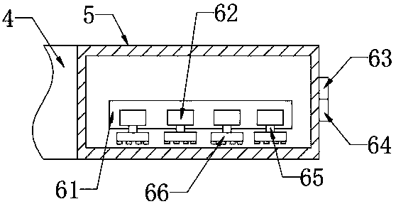
The invention provides a rebar scanning device comprising a handle, a scanner body, a scanning probe, a support plate, a solar cell, a lamp slot, an infrared lamp, a fixed block, a vibration motor, aspring shaft and a massage head, wherein the scanning probe is arranged on the lower side inside the scanner body; the solar cell is installed in the support plate which is mounted on the left end face of a display screen; the infrared lamp is arranged in the lamp slot which is opened on the lower end face of the support plate; to solve the problem of an original rebar scanner having no indicationfunction, the vibration motor is installed on the lower end face of the fixed block which is arranged inside the handle, and the massage head is mounted on the lower end surface of the spring shaft which is arranged on the lower end face of the vibration motor. The rebar scanning device solves the problem of an original rebar scanner having no massage function, and has the advantages of reasonable structure, convenient use, easy combination and installation, high security and high reliability.

Description

technical field [0001] The invention relates to a steel bar scanning device, which belongs to the technical field of steel bar processing equipment. Background technique [0002] The steel bar scanner is mainly used for the detection of steel bar distribution, diameter, direction, and the thickness of the concrete protective layer in the concrete structure of engineering buildings. Steel bar diameter, etc. In addition, the steel bar scanner can also detect the position of magnetic bodies and conductors in concrete structures, such as cables and plumbing pipes in walls, etc. Detection before construction can effectively avoid damage during construction. The damage of these facilities reduces the occurrence of accidents. Rebar scanner is an effective tool for construction process monitoring and quality inspection. [0003] In the prior art, the existing steel bar scanner does not have the function of indicating. When the staff scans the position of the steel bar with the ste...

Claims


Application Information

Patent Timeline
Patent Type & Authority Applications(China)
IPC IPC(8): G01C15/00A61H23/02
Inventor 王伟
Owner 王伟
Learn More