
Oil return structure of engine oil pump of engine

A technology of oil pump and engine, which is applied in the direction of engine lubrication, engine components, machines/engines, etc. It can solve the problems of easy wear of oil pump bearings and low service life of oil pumps, and achieve the effect of prolonging service life and reducing wear

Inactive Publication Date: 2018-03-09
GUANGXI YUCHAI MASCH CO LTD
View PDF6 Cites 4 Cited by
  • Summary
  • Abstract
  • Description
  • Claims
  • Application Information

AI Technical Summary

Problems solved by technology

[0006] The purpose of the present invention is to provide an engine oil pump oil return structure, so as to overcome the easy wear of the oil pump bearing and the low service life of the oil pump caused by the lubricating oil quickly falling back to the oil pan in the prior art when the engine stops running The problem

Method used


Image

  • Oil return structure of engine oil pump of engine
  • Oil return structure of engine oil pump of engine
  • Oil return structure of engine oil pump of engine

Examples


Embodiment Construction

[0022] The specific embodiments of the present invention will be described in detail below in conjunction with the accompanying drawings, but it should be understood that the protection scope of the present invention is not limited by the specific embodiments.

[0023] Unless expressly stated otherwise, throughout the specification and claims, the term "comprise" or variations thereof such as "includes" or "includes" and the like will be understood to include the stated elements or constituents, and not Other elements or other components are not excluded.

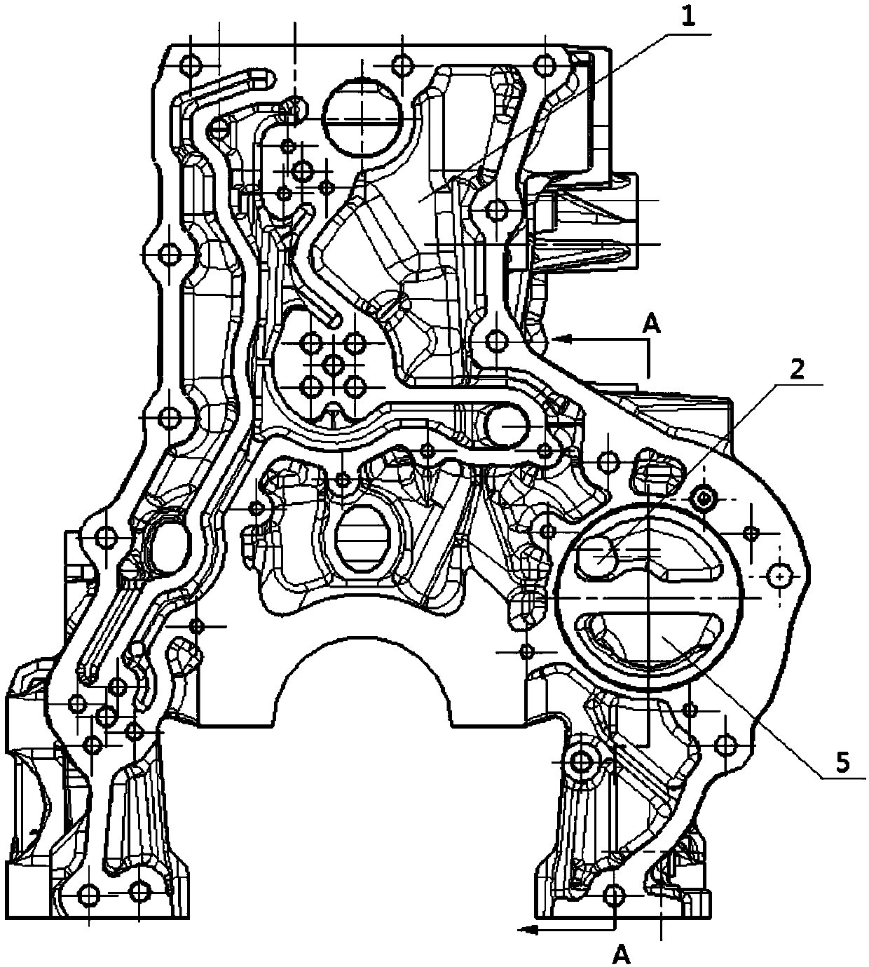
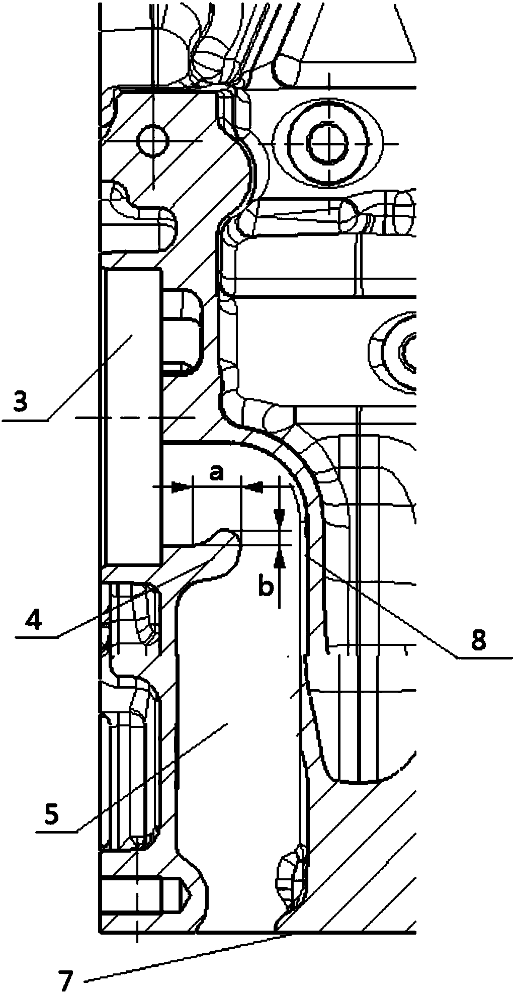
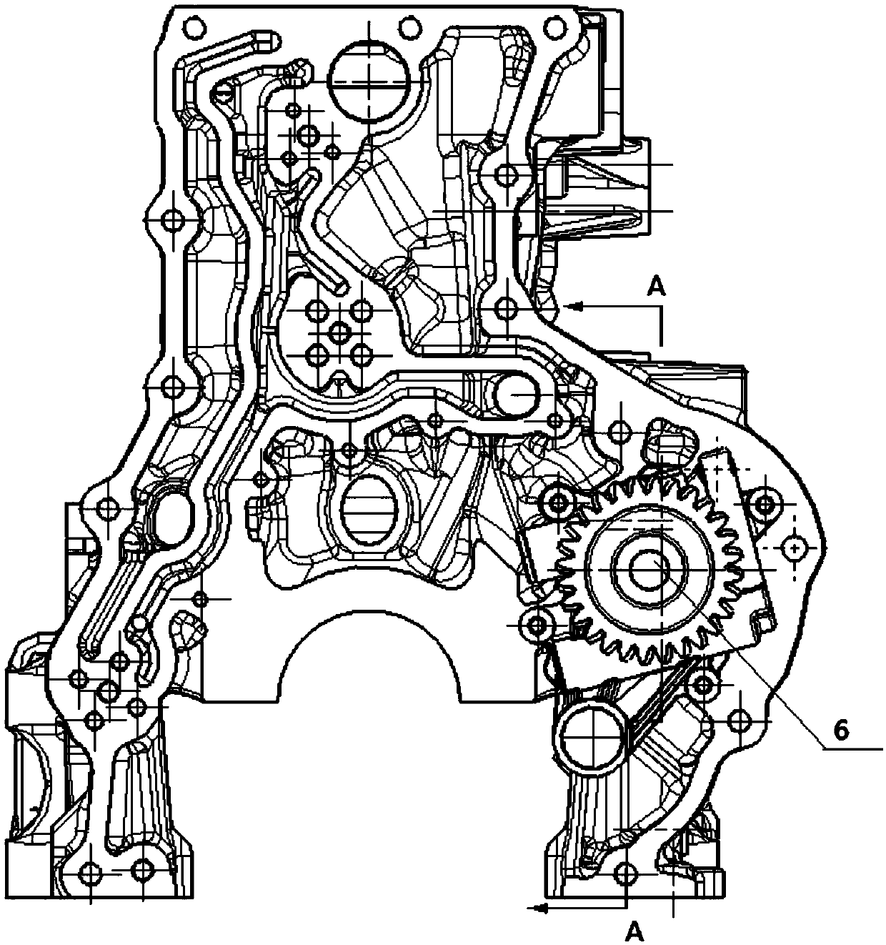
[0024] combine figure 1 and image 3 , The engine oil pump oil return structure of the engine of the present invention includes: a cylinder block 1, an oil pump 6, a main oil passage 2, an oil inlet passage 5 and an oil pan. Wherein the oil pan communicates with the oil inlet passage 5, the oil pump 6 and the main oil passage 2, and the upper end of the oil inlet passage 5 is provided with an anti-oil return rib structure...


PUM


Abstract

The invention discloses an oil return structure of an engine oil pump of an engine. The oil return structure comprises a cylinder block, an engine oil pump, a main oil duct, an engine oil incoming duct and an oil bottom shell, the oil bottom shell is communicated with the engine oil incoming duct, the engine oil pump and the main oil duct, and an oil-return-preventive convex rib structure is arranged at the upper end of the engine oil incoming duct and used for blocking part of engine oil to fall back into the oil bottom shell when an engine stops running. The oil return structure is reasonable in structural design; when the engine stops running, part of the engine oil can be stored around an engine oil pump mounting hole so as to continuously lubricate the engine oil pump, and wear of theengine oil pump when the engine is restarted is reduced, so that service life of the engine oil pump is prolonged.

Description

technical field [0001] The invention belongs to the technical field of engines and relates to an oil return structure of an engine oil pump. Background technique [0002] The lubrication system is to provide circulating oil to the relative moving parts of the engine, so as to reduce the resistance of the friction pair, and at the same time clean and cool the friction pair so that it can work smoothly. The engine lubricating oil is stored in the oil pan at the lower part of the engine. When the engine rotates, the rotor of the oil pump is driven to move, so that the oil pump absorbs oil from the oil pan, and the lubricating oil is sent to each lubricating part by the pressure generated by the oil pump. The lubricated lubricating oil returns to the oil pan through the oil return passage, and circulates repeatedly. [0003] Usually, an oil drain valve is set on the main oil passage or the oil pump, and its working principle is: when the oil pressure in the oil circuit of the e...

Claims


Application Information

Patent Timeline
Patent Type & Authority Applications(China)
IPC IPC(8): F01M1/02F01M11/02F01M11/00F01M1/10
CPCF01M1/02F01M1/10F01M11/0004F01M11/02F01M2001/0238F01M2001/0284F01M2001/105
Inventor 李壮徐雪松陈彪张雷
Owner GUANGXI YUCHAI MASCH CO LTD
Learn More