
Hydraulic ejection structure of plastic mold

A plastic mold and hydraulic technology, which is applied in the field of hydraulic ejection structure of plastic molds, can solve the problems of interference, short service life, easy crushing, etc., and achieve the effect of reducing space and long service life

Active Publication Date: 2020-01-17
MITAC PRECISION TECH(KUNSHAN) CORP
View PDF3 Cites 0 Cited by
  • Summary
  • Abstract
  • Description
  • Claims
  • Application Information

AI Technical Summary

Problems solved by technology

[0006] Therefore, the purpose of the present invention is to provide a hydraulic ejection structure for plastic molds, which solves the problems of short service life, easy crushing and interference with other structures of plastic molds in existing hydraulic ejection structures.

Method used


Image

  • Hydraulic ejection structure of plastic mold
  • Hydraulic ejection structure of plastic mold
  • Hydraulic ejection structure of plastic mold

Examples


Embodiment Construction

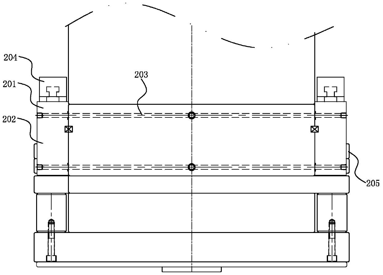
[0018] Please refer to image 3 , Figure 4 , image 3 Illustrated as the first angle sectional view of the hydraulic ejection structure of the plastic mold of the present invention, Figure 4 It is a sectional view of the hydraulic ejection structure of the plastic mold according to the present invention from a second viewing angle.

[0019] In order to achieve the above object, the hydraulic ejection structure of the plastic mold of the present invention comprises:

[0020] The hydraulic cylinder 201 is located on the die foot 202 of the plastic mold;

[0021] An oil passage 203 is located in the die foot 202 and communicates with the hydraulic cylinder 201;

[0022] One end of the connecting rod 204 is fixed to the telescopic end of the hydraulic cylinder 201, and the other end is fixed to the ejector plate 205 of the plastic mold.

[0023] Wherein, the oil passage 203 is established by drilling holes in the die foot 202 .

[0024] Wherein, the connecting rods 204 hav...


PUM


Abstract

The invention discloses a hydraulic ejection structure of a plastic mold. The hydraulic ejection structure comprises an oil hydraulic cylinder arranged on a mold foot of the plastic mold, an oil way arranged in the mold foot and communicated with the oil hydraulic cylinder, and a connecting rod; and one end of the connecting rod and a stretchable end of the oil hydraulic cylinder are fixed, and the other end of the connecting rod and an ejection plate of the plastic mold are fixed. Compared with the prior art, the hydraulic ejection structure of the plastic mold has the beneficial effects thatthe oil way is arranged in the mold foot of the plastic mold, and therefore an oil pipe is prevented from being damaged by pressing in the mold installing, mold detaching and transporting process; the oil pipe is arranged in the mold foot, the space is reduced, and interference with other structures of the outer side of the mold can be avoided; the service life is longer than that of the oil pipe; and after the oil hydraulic cylinder is installed, oil hydraulic cylinder detachment is not needed in the follow-up maintenance and mold detaching, and the problem of oil leakage does not exist.

Description

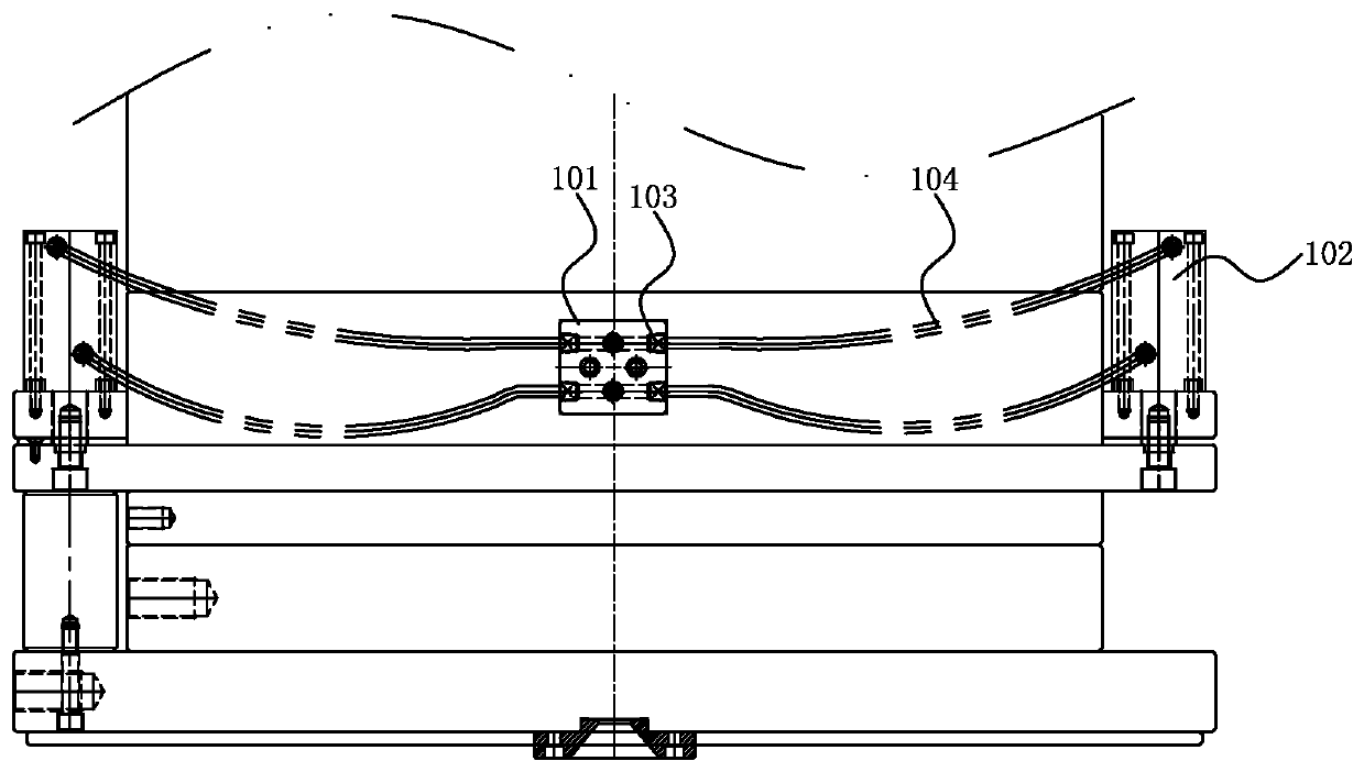
【Technical field】 [0001] The invention relates to a hydraulic ejection structure, in particular to a hydraulic ejection structure of a plastic mold. 【Background technique】 [0002] The plastic injection of the male mold is a commonly used mold structure in the design of plastic molds, and the injection molding of the male mold is basically ejected by hydraulic pressure (hydraulic cylinder). [0003] Please refer to figure 1 , figure 1 It is shown as a cross-sectional view of a hydraulic ejection structure of a plastic mold in the prior art, figure 2 It is a cross-sectional view of a hydraulic ejection structure of a plastic mold in the prior art at a second viewing angle. [0004] As shown in the figure, the hydraulic ejection structure includes a hydraulic cylinder 101 , an oil collecting block 102 , an oil pipe joint 103 and an oil pipe 104 . This structure has the following disadvantages: 1. Since the oil pipe 104 is arranged on the outside of the plastic mold, it is...

Claims


Application Information

Patent Timeline
Patent Type & Authority Patents(China)
IPC IPC(8): B29C33/46
CPCB29C33/46
Inventor 吴永兴曾桂桥
Owner MITAC PRECISION TECH(KUNSHAN) CORP
Learn More