
Proximity Jet Purifier

A jet exhaust and gas technology, applied in the purifier; field, can solve the problems of high maintenance cost, more energy consumption, unsatisfactory effect and so on

Active Publication Date: 2021-07-02
刘海云
View PDF4 Cites 1 Cited by
  • Summary
  • Abstract
  • Description
  • Claims
  • Application Information

AI Technical Summary

Problems solved by technology

[0003] Now in many places, PM2.5 exceeds the standard due to exhaust gas from factories, vehicle exhaust, sandstorms, etc. Once PM2.5 exceeds the standard, it will cause harm to human health. In order to deal with this hazard, many companies have manufactured many kinds of Air purifiers, but these air purifiers are either unsatisfactory, expensive, or follow-up maintenance costs are too high; according to current research, air containing excessive PM2.5 can wash away the dust and most of it when passing through water Toxic and harmful gas; but injecting air into water is a relatively energy-intensive method compared to other methods. Cubic meters per hour), fan motor power (W) = fan power (W) * 130% = air volume (L / S) * wind pressure (Kpa) / efficiency (75%) / force rate (75%) * 130 %=226(W), obviously, this power is relatively large compared to other methods, and this method, after the air enters the water to form bubbles, the air purification speed in the bubbles is very slow, so some washing air purification The device adopts atomization spray technology, but the spray technology relies on spraying liquid to clean the gas. This method is also a relatively energy-consuming technology, and it is not easy to handle or even consumes more energy. Although this technology is energy-saving, the effect is not satisfactory; therefore, it is necessary for us to provide an energy-saving and effective water-washing air purifier;

Method used

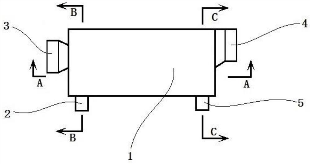
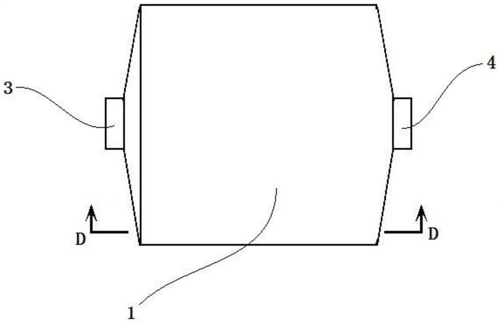
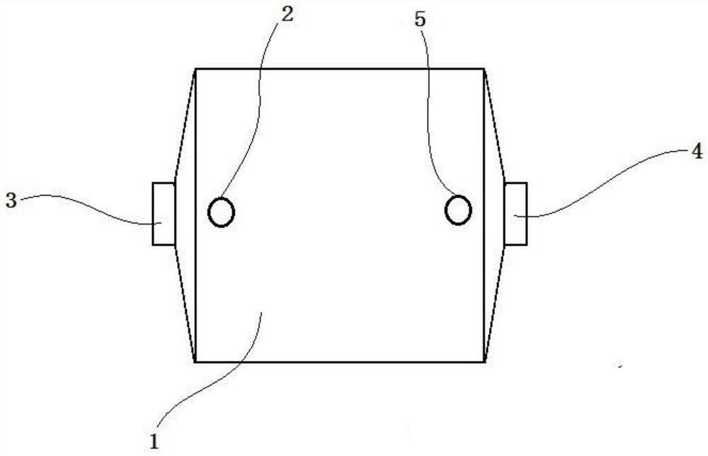

Image

  • Proximity Jet Purifier
  • Proximity Jet Purifier
  • Proximity Jet Purifier

Examples


Embodiment Construction

[0051] Figure 18 to Figure 25 Although the shown spray box group has a simple structure and takes up less space, it is difficult to clean when the small hole at the bottom of the spray row in the spray box is blocked, so we need to continue to optimize it;

[0052] The first embodiment is a detachable close-range jet purifier;

[0053] see Figure 26 , which is the design diagram of the optimized spray box group, which is the second spray box group in the present invention. The biggest feature of the spray box group is that all the air jet rows can be removed for cleaning; The spray box group is composed of three parts: the integrated box, the first jet row, and the general jet row; Figure 27 , 28, 29, 30, and 31 show an integrated box that integrates 5 spray tank shells, Figure 32 , 33 What , 34, 35 show is first with the jet row, comprises intake pipe 13, seal cover 704, bolt hole 712, jet row 6, small hole 7 on the first jet row, Figure 36 , 37 What , 38, 39 show ...


PUM


Abstract

In the present invention, the spray washing box is used as the working unit. Except for the air intake pipe, the exhaust pipe, the water inlet pipe and the drain pipe, the whole box shell of the spray washing box is completely closed. It is composed of one or more pipes, and the ends of these pipes are closed and small holes are opened at the bottom. When working, the air is pressed into the air jet row from the air intake pipe, and then sprayed from the small hole at the bottom of the air jet row to the water surface at the bottom of the spray tank and very close to the water surface for cleaning. The cleaned air flows out from the exhaust pipe and enters the spray tank. When the air flows through the water surface, it will leave dirt and take away part of the water. The clean water will flow into the replenishment spray tank from the water inlet pipe, and the dirty water and the dirt left will flow out from the drain pipe. Due to the air in the present invention The depth of entering the water is not large, so it is very energy-saving. After connecting a plurality of spray washing box units in the present invention, a water-washing air purifier with a very good purification effect can be realized. The present invention calls it a close-range air jet purifier.

Description

technical field [0001] The invention provides a purifier using water to wash air; [0002] Background of the invention [0003] Now in many places, PM2.5 exceeds the standard due to exhaust gas from factories, vehicle exhaust, sandstorms, etc. Once PM2.5 exceeds the standard, it will cause harm to human health. In order to deal with this hazard, many companies have manufactured many kinds of Air purifiers, but these air purifiers are either unsatisfactory, expensive, or follow-up maintenance costs are too high; according to current research, air containing excessive PM2.5 can wash away the dust and most of it when passing through water Toxic and harmful gas; but injecting air into water is a relatively energy-intensive method compared to other methods. Cubic meters per hour), fan motor power (W) = fan power (W) * 130% = air volume (L / S) * wind pressure (Kpa) / efficiency (75%) / force rate (75%) * 130 %=226(W), obviously, this power is relatively large compared to other met...

Claims


Application Information

Patent Timeline
Patent Type & Authority Patents(China)
IPC IPC(8): B01D47/06
CPCB01D47/06
Inventor 刘海云
Owner 刘海云
Learn More