
Vacuum potting process

A potting and process technology, applied in the field of new energy vacuum potting technology, can solve the problems of low partial discharge initial voltage, ignition between lines, imbalance of resin and curing agent ratio, etc., to eliminate volume shrinkage internal stress, avoid Shrinkage effect

Pending Publication Date: 2018-03-06
SHENZHEN XETAR TECH
View PDF0 Cites 5 Cited by
  • Summary
  • Abstract
  • Description
  • Claims
  • Application Information

AI Technical Summary

Problems solved by technology

[0002] The new energy vehicle industry is a strategic emerging industry focused on by the state. Especially after the State Council promulgated policies such as exemption from purchase tax in July 2014, the production and sales of new energy vehicles have continued to blow out; however, due to the complex environment in which new energy motors are used In order to meet the requirements of its extremely high withstand voltage strength, dielectric strength, thermal conductivity and heat resistance, mechanical strength, electrical strength and noise, the usual practice is to impregnate and pot the motor stator. Treatment; although dipping treatment can improve the mechanical strength, thermal conductivity and heat resistance, electrical strength and external environment resistance of the motor stator, it is far from enough for new energy motors with high power, small volume, high efficiency and energy saving; Although the sealing treatment can meet its requirements, there are still problems: the product has air bubbles or gaps between lines, resulting in low partial discharge inception voltage, ignition between lines and product breakdown
[0006] Component A in AB glue has been stored for a long time and precipitated, and it was not fully stirred before use, resulting in an imbalance in the actual ratio of resin and curing agent; component B was stored open for a long time, and it failed to absorb moisture; the potting parts were not timely in high humidity seasons. Entering the curing process, the surface of the object absorbs moisture

Method used


Image

  • Vacuum potting process
  • Vacuum potting process
  • Vacuum potting process

Examples


Embodiment Construction

[0035] Embodiments of the present invention will be described in detail below. It should be emphasized that the following description is only exemplary and not intended to limit the scope of the invention and its application.

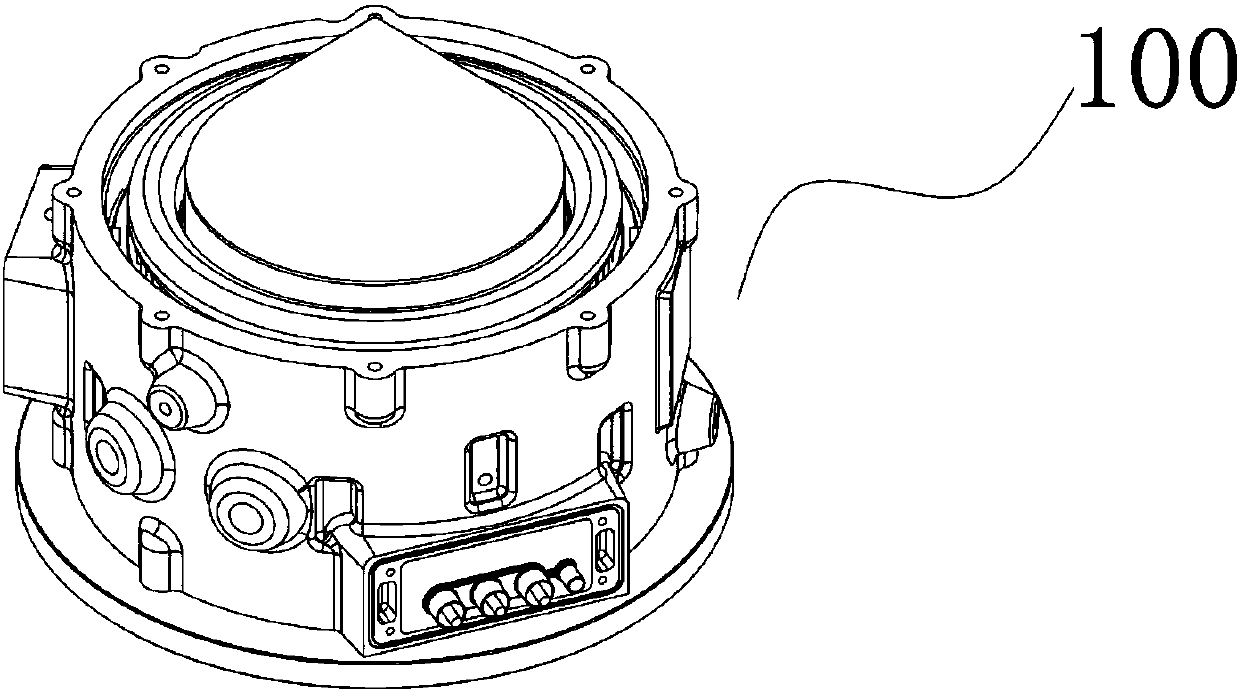
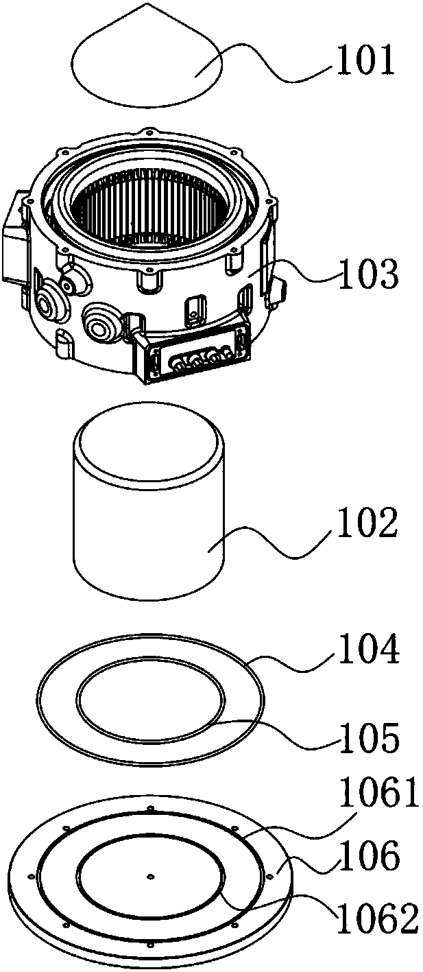
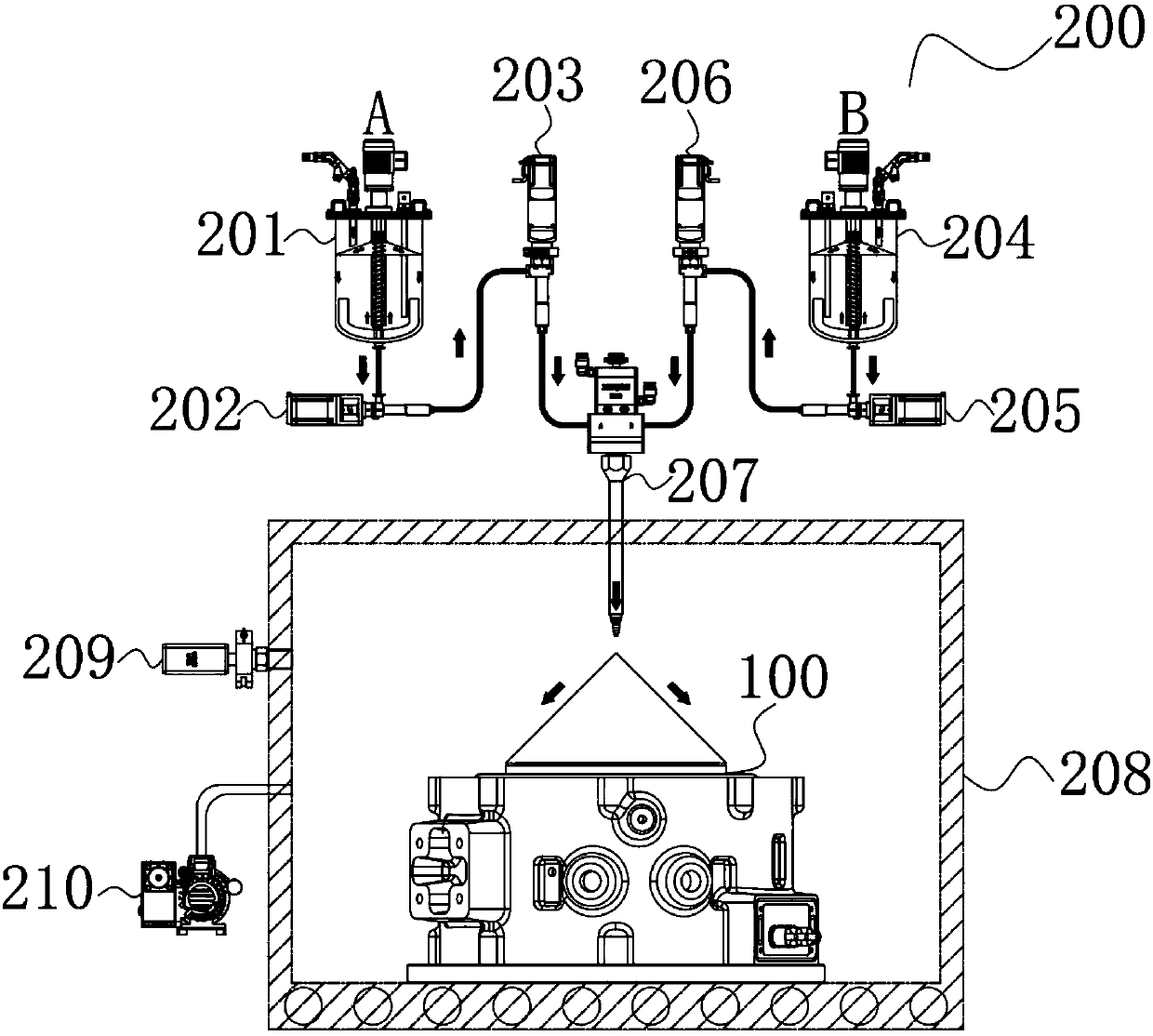
[0036] The invention provides a potting device for a stator of a new energy motor. refer to Figure 1 to Figure 3 , the potting device for the new energy motor stator includes a potting fixture 100 and a vacuum potting device 200, the potting fixture 100 is placed in the inner cavity of the vacuum potting device 200, and the potting fixture 100 includes a fixture guide umbrella 101, a fixture mandrel 102. The first sealing ring 104 of the fixture, the second sealing ring 105 of the fixture and the fixture base 106; the fixture base 106 is connected to the mandrel 102 of the fixture, and the second sealing ring 105 of the fixture is arranged on the second sealing groove 1062 of the fixture base 106, so that The fixture base 106 and the fixture mandrel ...


PUM


Abstract

The invention provides a vacuum potting process. The vacuum potting process includes following steps: performing demoulding processing on a clamp; assembling the clamp; preheating a to-be-potted device; performing multi-segment potting in a vacuum environment; performing curing processing on the potted device; and performing demoulding on the device after completion of potting. According to the vacuum potting process, the device is fully preheated, the viscosity of glue potted into the device can be rapidly reduced, infiltration is guaranteed, and the influence of moisture on the potting effect is avoided; and the multi-segment potting process is performed in the vacuum environment, air in gaps between components in the device can be completely eliminated, the infiltration of the glue intothe gaps can be guaranteed, and bubbles or gaps can be avoided.

Description

technical field [0001] The invention relates to the field of potting, in particular to a new energy vacuum potting process. Background technique [0002] The new energy vehicle industry is a strategic emerging industry focused on by the state. Especially after the State Council promulgated policies such as exemption from purchase tax in July 2014, the production and sales of new energy vehicles have continued to blow out; however, due to the complex environment in which new energy motors are used In order to meet the requirements of its extremely high withstand voltage strength, dielectric strength, thermal conductivity and heat resistance, mechanical strength, electrical strength and noise, the usual practice is to impregnate and pot the motor stator. Treatment; although dipping treatment can improve the mechanical strength, thermal conductivity and heat resistance, electrical strength and external environment resistance of the motor stator, it is far from enough for new en...

Claims


Application Information

Patent Timeline
Patent Type & Authority Applications(China)
IPC IPC(8): H02K15/12
CPCH02K15/12
Inventor 袁尊钢刘自华
Owner SHENZHEN XETAR TECH
Learn More