
Novel mixing and blending tank

A new technology of mixing and blending, which is applied in the direction of mixers, mixers with rotating stirring devices, mixer accessories, etc., can solve problems such as uneven mixing, failure to meet standards, inconvenient feeding, etc., to achieve convenient feeding, The material is mixed evenly and the effect of improving quality

Inactive Publication Date: 2018-03-06
CHENGDU RONGCHUANG ZHIGU SCI & TECH
View PDF0 Cites 2 Cited by
  • Summary
  • Abstract
  • Description
  • Claims
  • Application Information

AI Technical Summary

Problems solved by technology

However, the vertical tank feed inlet is generally located above the tank body, so it is inconvenient to feed materials; at the same time, the traditional blending tank does not stir evenly during the mixing process, resulting in poor mixing effect of the materials and failing to achieve to standard

Method used


Image

  • Novel mixing and blending tank

Examples


Embodiment 1

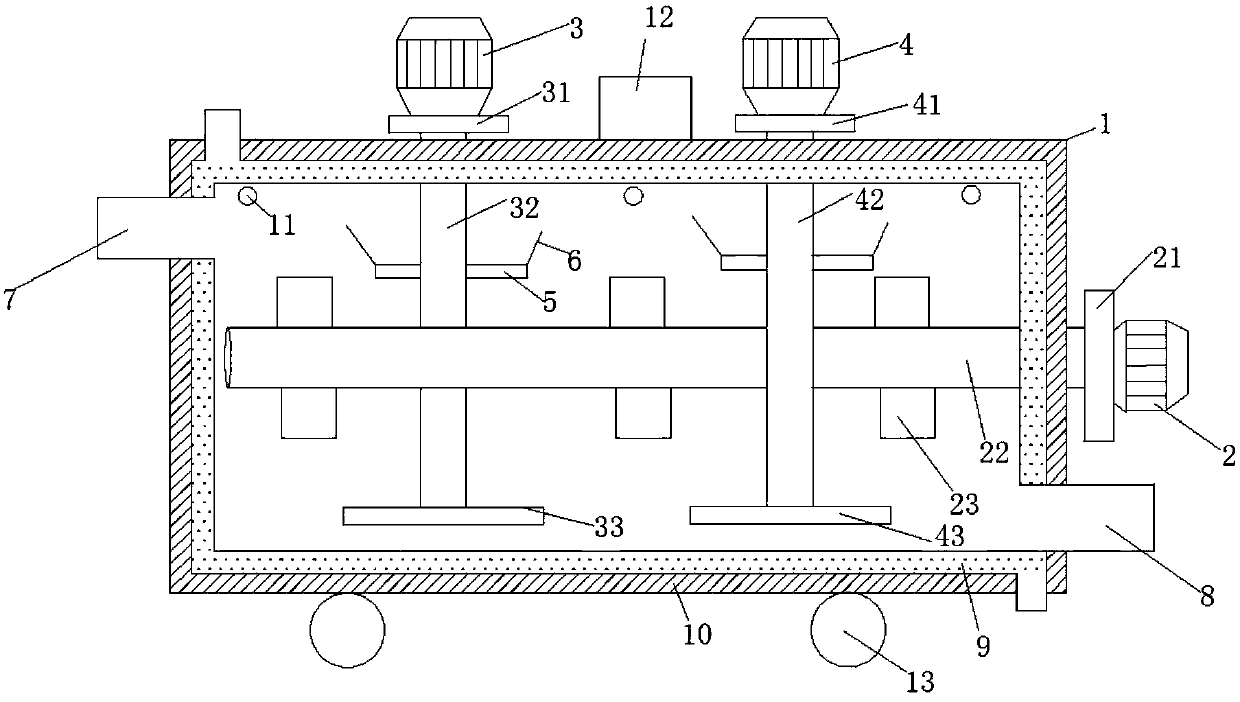
[0024] Such as figure 1 As shown, a new type of mixing and blending tank includes a tank body 1, a feed port 7 and a discharge port 8 respectively located on the left and right sides of the tank body 1, a first motor 2 located on the right side of the tank body 1, and a first transmission device 21, the first stirring shaft 22 located inside the tank, the first motor 2 is connected to the first transmission device 21, the first transmission device 21 is connected to the first stirring shaft 22, and the first The stirring shaft 22 is provided with 4-6 first stirring paddles 23; it also includes a second motor 3 and a second transmission device 31 positioned on the left side of the top of the tank body 1, and a second stirring shaft 32 positioned inside the tank body 1, so The second motor 3 is connected with the second transmission device 31, the second transmission device 31 is connected with the second stirring shaft 32, and the second stirring shaft 32 is provided with a sec...

Embodiment 2

[0027] Based on Example 1, such as figure 1 As shown, the outer wall of the tank body 1 is provided with a steam heating interlayer 9 , and the outer wall of the steam heating interlayer 9 is provided with an insulating layer 10 . If the prepared material needs to be heated, the material in the tank can be heated through the steam heating layer 9, and the insulation layer 10 plays a role of heat preservation, prevents the diffusion of hot gas, and enhances the heating effect. In addition to steam heating, the heating device can also be used to set electric heating wires in the interlayer for electric heating; at the same time, the insulation layer can also be vacuumed and insulation materials can be added for insulation.

Embodiment 3

[0029] A temperature sensor 11 is provided inside the tank body 1 , and the temperature sensor 11 is electrically connected to a temperature display 12 . The temperature sensor 11 inside the tank body 1 can monitor the temperature change in the tank body 1 from time to time, and display it through the temperature display 12 electrically connected to the temperature sensor 11, so as to understand the condition of the internal temperature of the tank body.


PUM


Abstract

The invention discloses a novel mixing tank, which comprises a tank body, a material inlet and a material outlet located on the left and right sides of the tank body, a first motor located on the right side of the tank body and connected to a first transmission device, the first The transmission device is connected to the first stirring shaft located inside the tank, and the first stirring shaft is provided with 4-6 first stirring paddles; the second motor located on the left side of the top of the tank is connected to the second transmission device , the second transmission device is connected with the second stirring shaft located inside the tank body, and the second stirring shaft is provided with a second stirring paddle; the third motor located on the left side of the top of the tank body is connected with the third transmission device, The third transmission device is connected with the third stirring shaft inside the tank, and the third stirring shaft is provided with a second stirring paddle; the first stirring paddle, the second stirring paddle and the third stirring paddle are not in contact with each other. The equipment is a new type of mixing tank, which is convenient for feeding and moving, and can make the material mix more evenly and improve the mixing quality.

Description

technical field [0001] The invention relates to the technical field of industrial equipment, in particular to a novel mixing tank. Background technique [0002] Mixing tank, also known as mixing tank and mixing tank, has the advantages of energy saving, corrosion resistance, strong production capacity, convenient cleaning, simple structure, etc. It is mainly used for mixing milk products, sugar, beverages, food and other elements with various drugs. Afterwards, it can be stirred evenly for storage, and it is an indispensable equipment for manufacturers of dairy products, beverages, and pharmaceuticals. Traditional blending tanks are generally vertical, and are usually equipped with a tank body, a tank cover, a stirring paddle, a material inlet, and a discharge valve, and the stirring paddle plays a stirring role. However, the vertical tank feed inlet is generally located above the tank body, so it is inconvenient to feed materials; at the same time, the traditional blending...

Claims


Application Information

Patent Timeline
Patent Type & Authority Applications(China)
IPC IPC(8): B01F7/00B01F15/02B01F15/06
Inventor 章显红
Owner CHENGDU RONGCHUANG ZHIGU SCI & TECH
Learn More