
Waste gas treatment equipment and process

A waste gas treatment equipment and waste gas treatment technology, applied in gas treatment, membrane technology, dispersed particle separation, etc., can solve the problems of high waste gas treatment cost, unreusable activated carbon, and expensive treatment cost, achieving low power and simple structure. , the effect of small footprint

Pending Publication Date: 2018-03-06
绍兴市英强橡塑科技有限公司
View PDF0 Cites 2 Cited by
  • Summary
  • Abstract
  • Description
  • Claims
  • Application Information

AI Technical Summary

Problems solved by technology

The combustion method is suitable for the treatment of flammable gases, which requires a large amount of fuel consumption, high processing costs, and is prone to secondary pollution
The water absorption method is suitable for water-soluble gases, which consumes a lot of water and has low purification efficiency
Although the activated carbon adsorption method has a good adsorption effect, it is expensive, and the activated carbon after the adsorption is complete cannot be used again. In actual use, the activated carbon often needs to be replaced at short intervals, so its treatment cost is very expensive.
[0003] Moreover, the above-mentioned waste gas treatment tower, the combustion tower used in the combustion method, and the equipment used in water treatment are all very large, and the energy consumption is high (basically hundreds or thousands of power), so the current waste gas treatment cost remains high

Method used

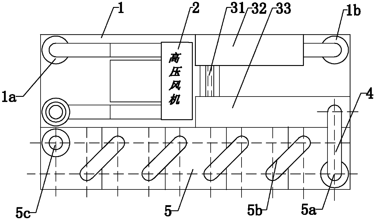
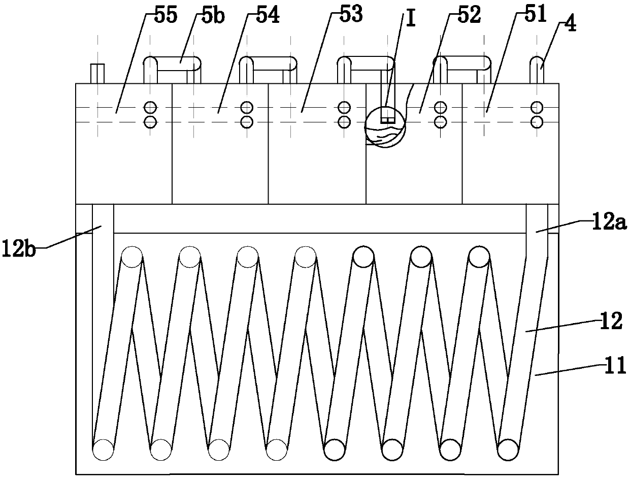
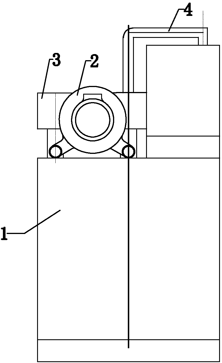

Image

  • Waste gas treatment equipment and process
  • Waste gas treatment equipment and process
  • Waste gas treatment equipment and process

Examples


Embodiment 1

[0036] like figure 1 , figure 2 and image 3 As shown, the waste gas treatment equipment includes a high-pressure blower 2, a cooling device 1, a waste gas treatment pipeline and a micro-processing device 5 connected in sequence, and the waste gas inlet of the high-pressure blower 2 is directly connected with the waste gas outlet of the equipment in the factory or through exhaust and connectivity. The cooling device 1 is mainly composed of a cooling box 11 and a cooling coil 12 . The cooling spiral pipe 12 is arranged in the cooling box 11 , and its size is adapted to the cooling box 11 . The inlet and outlet of the cooling coiled pipe 12 are fixed and drawn out on the side wall at the top of the cooling box 11 , and the cooling coiled tube 12 is not connected to the inside of the cooling box 11 . The top of the cooling device 1 is provided with an exhaust gas inlet-1a and an exhaust gas outlet-1b, and the exhaust gas inlet-1a communicates with the exhaust gas outlet of t...

Embodiment 2

[0046] The difference between this embodiment and Embodiment 1 is that: the air inlet of the high-pressure fan 2 is provided with a spraying device. The spraying device is used to cool down the exhaust gas and perform preliminary treatment on the exhaust gas to reduce the content of large particles and water-soluble substances in the exhaust gas for subsequent exhaust gas treatment.

Embodiment 3

[0048] like Image 6 As shown, the difference between this embodiment and Embodiment 1 is that: the gas outlet 5b of the exhaust gas treatment pipeline or the gas outlet 5b of the cooling device 1 or the gas outlet 5b of the micro-processing device 5 is provided with an ejector, and the ejector includes diameters in order Increased interior pipe 73, middle pipe 72, outer pipe 71, interior pipe 73 two ends open, and its inside is stuffed with loofah 74; Middle pipe 72 bottom opening and outer sleeve on the inner pipe 73, its top is closed. The outer tube 71 is overlaid on the inner tube 73 and wraps the middle tube 72. The bottom end of the outer tube 71 is sealed and fixedly connected to the side wall of the inner tube 73. The top of the outer tube 71 is provided with an opening to communicate with the outside world, and the air outlet 5b discharges The exhaust gas passes through the inner pipe 73 , the middle pipe 72 and the outer pipe 71 in sequence and then is discharged. ...


PUM


Abstract

The invention provides waste gas treatment equipment and exhaust gas treatment process, and belongs to the field of waste gas treatment. The waste gas treatment equipment comprises a cooling device and a waste gas treatment pipeline, wherein an air outlet of the cooling device is connected with the waste gas treatment pipeline; the waste gas treatment pipeline is filled with a loofah sponge; the waste gas treatment pipeline comprises an inlet pipe, an intermediate pipe and an outlet pipe which communicate in sequence; the pipe diameter of the intermediate pipe is smaller than those of the inlet pipe and the outlet pipe; one end of the inlet pipe is provided with a gas inlet communicating with the cooling device; and one end of the outlet pipe is provided with an gas outlet. The treatment process comprises three steps of cooling, reducing treatment and micro-treatment. The waste gas treatment equipment provided by the invention has the advantages of simple structure, small volume, smalloccupied area, small power, and low manufacturing cost; and the waste gas treatment process has the advantages of less steps, short flow and convenient operation, can greatly reduce the waste gas treatment cost, and is suitable for treating waste gases generated by various industries of rubber and plastic, cast iron, paint spraying and the like.

Description

technical field [0001] The invention relates to the field of waste gas treatment, in particular to a waste gas treatment equipment and process. Background technique [0002] Enterprises will produce various waste gases in the process of production and processing. Untreated waste gases directly discharged into the atmosphere will cause serious air pollution, destroy ecology and endanger human health and living environment. At present, the commonly used waste gas treatment methods are activated carbon adsorption, water absorption and combustion, etc., and most of them use waste gas treatment towers to treat waste gas. The combustion method is suitable for the treatment of flammable gases, which requires a large amount of fuel consumption, high processing costs, and is prone to secondary pollution. The water absorption method is suitable for water-soluble gases, which consumes a lot of water and has low purification efficiency. Although the activated carbon adsorption method ...

Claims


Application Information

Patent Timeline
Patent Type & Authority Applications(China)
IPC IPC(8): B01D53/04
CPCB01D53/04B01D2253/202B01D2259/652B01D2257/90
Inventor 单达华
Owner 绍兴市英强橡塑科技有限公司
Learn More