
Welding and weld mark polishing device for machining of electrical heated tube

An electric heating tube and welding mark technology, applied in the field of electric heating tube processing equipment, can solve problems such as affecting the overall rigidity of the electric heating tube, the electric heating tube is easy to break, and the electric heating tube failure, etc., and achieves the effect of ensuring market demand, saving time, and saving costs.

Inactive Publication Date: 2018-02-27
湖州绅博能源科技有限公司
View PDF8 Cites 30 Cited by
  • Summary
  • Abstract
  • Description
  • Claims
  • Application Information

AI Technical Summary

Problems solved by technology

[0004] Aiming at the deficiencies of the prior art, the present invention provides a welding and weld mark grinding device for electric heating tube processing, which solves the need to weld the outer tube during the processing of the existing electric heating tube to ensure that the electric heating tube is in any It can work under all conditions, avoid water leakage and other phenomena, which will cause the electric heating tube to fail, and after welding, the weld marks will affect the overall rigidity of the electric heating tube, causing it to produce stress concentration points, making the electric heating tube easy to break and thus damaged.

Method used


Image

  • Welding and weld mark polishing device for machining of electrical heated tube
  • Welding and weld mark polishing device for machining of electrical heated tube
  • Welding and weld mark polishing device for machining of electrical heated tube

Examples


Embodiment Construction

[0026] The following will clearly and completely describe the technical solutions in the embodiments of the present invention with reference to the accompanying drawings in the embodiments of the present invention. Obviously, the described embodiments are only some, not all, embodiments of the present invention. Based on the embodiments of the present invention, all other embodiments obtained by persons of ordinary skill in the art without making creative efforts belong to the protection scope of the present invention.

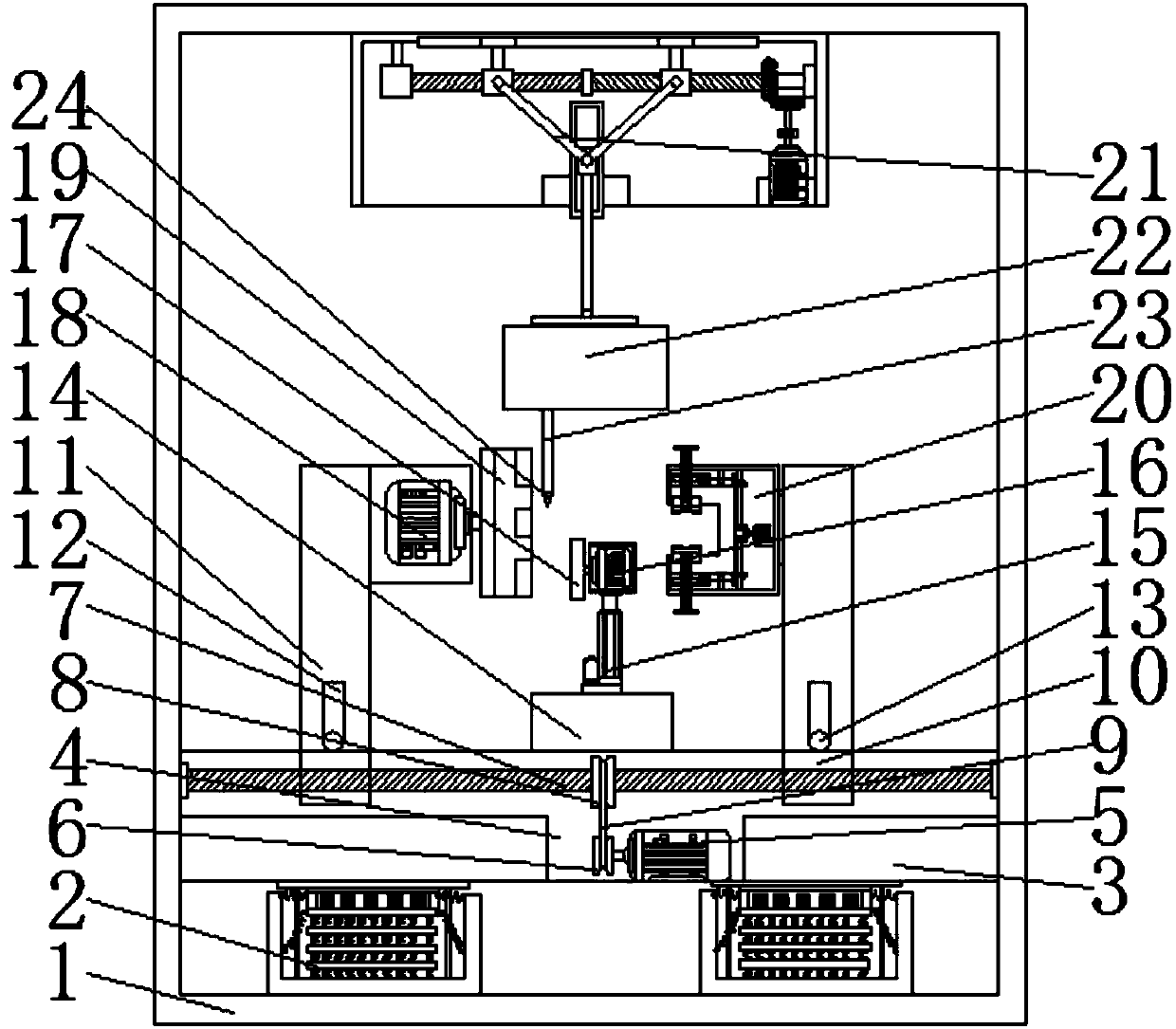
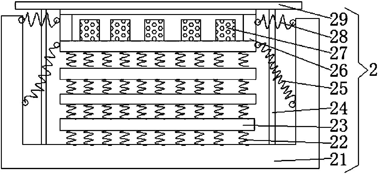
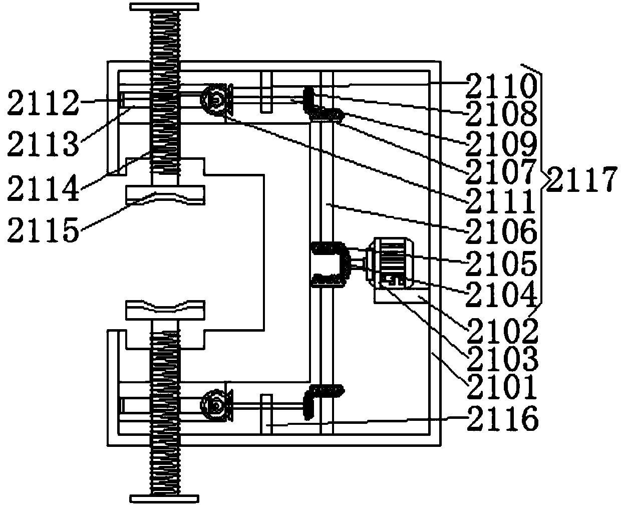
[0027] see Figure 1-5, the present invention provides a technical solution: a welding and weld mark grinding device for electric heating tube processing, including a box body 1, a shock absorbing device 2 is fixedly connected to the bottom of the inner cavity of the box body 1, and the shock absorbing device 2 includes a shock absorbing bottom plate 201 A plurality of damping springs 202 are fixedly connected to the bottom of the inner surface of the damping ...


PUM


Abstract

A welding and weld mark polishing device for machining of an electrical heated tube comprises a box, wherein the bottom of a cavity of the box is fixedly connected with a damping device; the side, which is away from a supporting block, of a supporting table is fixedly connected with a lifting device; an output shaft of a second motor is rotatably connected with a polishing wheel through a coupler;an output shaft of a third motor is rotatably connected with a three-jaw chuck through a coupler; the top of the side, which is positioned on the right side of the polishing wheel and is close to thegrinding wheel, of the supporting rod is rotatably connected with a fixing device; the middle of the top of the cavity of the box is fixedly connected with a vertical movement device; and the side, which is away from the top of the cavity of the box, of the vertical movement device is fixedly connected with a welding box. The invention relates to the technical field of electrical heated tube machining equipment. Any types of electrical heated tubes can be fixed, machining equipment does not need to be changed frequently, the cost is saved, industrial development is facilitated, a point of weld can be found automatically, manual operation is not required, the device is safe and reliable, the production efficiency is improved, the time is saved, and thus, market requirements are met.

Description

technical field [0001] The invention relates to the technical field of electric heating tube processing equipment, in particular to a welding and weld mark grinding device for electric heating tube processing. Background technique [0002] Electric heating tube, also known as heating tube, heating tube, scientific name tubular electric heater element, is to put a coiled heating wire in a metal tube, and fill it with good heat resistance, thermal conductivity and insulation around it and in the gap. Non-toxic insulating powder, the two ends of the heating wire have lead-out rods or lead-out wires. It has the characteristics of simple structure, high mechanical strength, high thermal efficiency, safety and reliability, easy installation and long service life. It is widely used in various saltpeter tanks, water tanks, oil tanks, acid-base tanks, fusible metal melting furnaces, air heating furnaces, drying furnaces, drying ovens, hot pressing molds and other devices. The elect...

Claims


Application Information

Patent Timeline
IPC IPC(8): B23K37/02B23K37/053B24B9/04
CPCB23K37/0247B23K37/0538B24B9/04
Inventor 何炎桥
Owner 湖州绅博能源科技有限公司
Learn More