
Fish killing machine

A fish killing machine and frame technology, which is applied in fish processing, fish cleaning/descaling, slaughtering, etc., can solve the problems of unfavorable physical and mental health of workers, unsuitable for home use, complex structure, etc., achieve high market promotion value, and reduce occupation The effect of high space and work efficiency

Active Publication Date: 2018-02-27
JINGZHOU JICHUANG ELECTROMECHANICAL TECH CO LTD
View PDF4 Cites 1 Cited by
  • Summary
  • Abstract
  • Description
  • Claims
  • Application Information

AI Technical Summary

Problems solved by technology

At present, fish are generally killed by purely manual methods. It is acceptable for a single family to use this method of killing fish, but for shops or restaurants that specialize in selling fish, this method of killing fish is relatively inefficient and expensive. The labor intensity of the workers is high. In addition, the method of killing fish in the cold winter is not conducive to the physical and mental health of the workers, especially when the palms of the hands are exposed to cold water for a long time, they are prone to frostbite or other diseases.
[0003] In order to solve the above technical problems, a mechanical device for killing fish has been introduced. The existing fish killing device is bulky and complex in structure, and is not suitable for household use. The transmission mechanism of the fish killing device mostly adopts a belt or chain, the transmission distance is relatively large, and it is easy to wear and tear, resulting in a short service life of the fish killing device

Method used


Image

  • Fish killing machine
  • Fish killing machine
  • Fish killing machine

Examples


Embodiment Construction

[0031] The present invention will be described in further detail below in conjunction with the accompanying drawings and embodiments, so that those skilled in the art can implement it with reference to the description.

[0032] It should be understood that terms such as "having", "comprising" and "including" as used herein do not entail the presence or addition of one or more other elements or combinations thereof.

[0033] It should be noted that the experimental methods described in the following embodiments, unless otherwise specified, are conventional methods, and the reagents and materials, unless otherwise specified, can be obtained from commercial sources.

[0034] In the description of the present invention, the terms "transverse", "longitudinal", "upper", "lower", "front", "rear", "left", "right", "vertical", "horizontal", " The orientations or positional relationships indicated by "top", "bottom", "inner", "outer", etc. are based on the orientations or positional rel...


PUM


Abstract

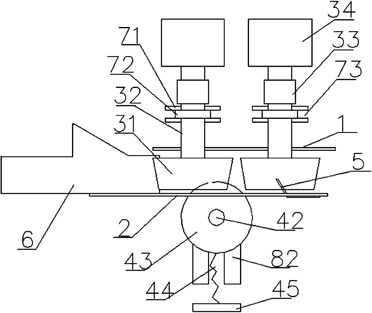
The invention discloses a fish killing machine. The fish killing machine comprises a rack, an upper plate body and a lower plate body which are arranged up and down in parallel, a transmission device,a paunching cutter mechanism and a scraping plate, wherein the upper surface of the upper plate body is fixedly connected with the rack, and the upper plate body is arranged in an inclined manner andkeeps a certain included angle with the horizontal plane; a strip-shaped first through hole and a square second through hole which are communicated with each other are formed in the lower plate body;the transmission device comprises two pairs of toothed roller mechanisms, each pair of toothed roller mechanism comprises two toothed rollers, two toothed roller shafts, two couplers and two first motors; the paunching cutter mechanism comprises a second motor, a spindle, a paunching cutter and a compression spring; and the scraping plate comprises a first part and a second part which are fixedlyarranged on the lower surface of the lower plate body. The fish killing machine disclosed by the invention has the advantages that the size of a feeding channel can be regulated self according to thesize of a fish, so that fishes with different sizes can be slaughtered; meanwhile, structure is simple, and working efficiency is relatively high, so that the fish killing machine disclosed by the invention has relatively high market promotion value.

Description

technical field [0001] The invention relates to the field of aquatic product processing machinery. More specifically, the present invention relates to a fish killing machine. Background technique [0002] Fish is a high-nutrition, low-fat food that is becoming more and more popular. Before cooking fish, it needs to be killed first. At present, fish are generally killed by purely manual methods. It is acceptable for a single family to use this method of killing fish, but for shops or restaurants that specialize in selling fish, this method of killing fish is relatively inefficient and expensive. The labor intensity of the workers is high. In addition, adopting this method of killing fish in the cold winter is not conducive to the physical and mental health of the workers, especially when the palms are exposed to cold water for a long time, they are prone to frostbite or other diseases. [0003] In order to solve the above-mentioned technical problems, a mechanical device f...

Claims


Application Information

Patent Timeline
IPC IPC(8): A22C25/00A22C25/02A22C25/08A22C25/14
CPCA22C25/00A22C25/02A22C25/08A22C25/145Y02A40/81
Inventor 周晗生李平
Owner JINGZHOU JICHUANG ELECTROMECHANICAL TECH CO LTD
Learn More