High-speed motor rotation tester

A high-speed motor and tester technology, applied in the field of testing, can solve problems such as production problems and cost waste, and achieve the effect of avoiding dropping or scratching, avoiding waste, and ensuring normal operation

Inactive Publication Date: 2018-02-23
丰源昭和(天津)科技发展有限公司
View PDF0 Cites 0 Cited by
  • Summary
  • Abstract
  • Description
  • Claims
  • Application Information

AI Technical Summary

Problems solved by technology

[0002] The motor needs to be rotated at the same speed during use. When the motor has a problem and the speed exceeds the range of use, the staff cannot find it in time, which leads to production problems and waste of cost. Therefore, there is an urgent need for temporary detection equipment during production.

Method used


Image

  • High-speed motor rotation tester
  • High-speed motor rotation tester
  • High-speed motor rotation tester

Examples


Embodiment 1

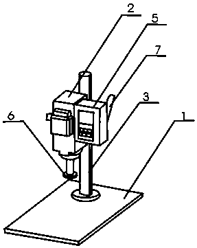
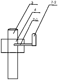
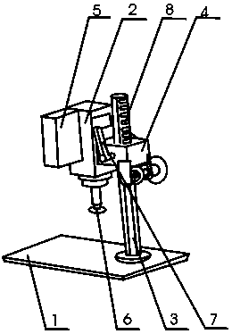
[0016] The invention provides a high-speed motor rotation tester, which includes a base 1, a motor frame 2, a support column 3, a fixed frame 4, a controller 5, a speed measuring magnetic ring 6, a fixed handle 7, and a fixed hole 8. The upper side of the base 1 is equipped with The support column 3 is provided with a fixing hole 8 on the support column 3, and a fixed frame 4 is installed on the upper side of the support column 3. The fixed handle 7 passes through the fixed frame 4 and is connected to the support column 3. The fixed frame 4 is connected to the motor frame 2, and the motor frame 2. A motor is installed inside, and a speed-measuring magnetic ring 6 is installed on the lower side of the motor frame 2. The side of the motor frame 2 is connected to the controller 5, and the controller 5 is connected to the motor and the speed-measuring magnetic ring 6 respectively. The fixed handle 7 includes a fixed head 7-1, a control handle 7-2, and the control handle 7-2 is conn...

Embodiment 2

[0018] When in use, place the motor in the motor frame 2, and then adjust the position of the motor frame 2 according to the motor model. When adjusting, move the fixed handle 7, and then move the fixed frame 4. When moving to a suitable position, fix the fixed handle 7 The head 7-1 is placed in the fixing hole 8 of the support column 3, the fixing frame 4 is fixed, and then the motor in the motor frame 2 is fixed, and then the controller 5 is opened, and the motor is tested through the speed measuring magnetic ring 6 and The data is transmitted to the controller 5, and the controller 5 records and controls it. When the rotation speed exceeds the range of use, it is convenient for the staff to find out in time, ensuring the normal production, avoiding waste of costs, and saving costs.


PUM


Abstract

The invention provides a high-speed motor rotation tester, which is characterized in that it includes a base, a motor frame, a support column, a fixed frame, a controller, a speed measuring magnetic ring, a fixed handle, and a fixing hole, and a support column is installed on the upper side of the base. A fixing hole is provided on the supporting column, a fixing frame is installed on the upper side of the supporting column, and the fixing handle is connected through the fixing frame and the supporting column. The present invention is a high-speed motor rotation tester. The motor is installed on the Inside the motor frame, the setting of the motor frame facilitates the placement of the motor, prevents the motor from falling or being scratched during the test, and protects the motor. In the present invention, the speed-measuring magnetic ring is installed on the lower side of the motor frame, which facilitates the speed-measuring function of the speed-measuring magnetic ring.

Description

technical field [0001] The invention relates to the testing field, in particular to a high-speed motor rotation tester. Background technique [0002] The motor needs to be rotated at the same speed during use. When the motor has a problem and the speed exceeds the range of use, the staff cannot find it in time, resulting in production problems and cost waste. Therefore, there is an urgent need for temporary testing equipment during production. Contents of the invention [0003] According to the above technical problems, the present invention provides a high-speed motor rotation tester, which is characterized in that it includes a base, a motor frame, a support column, a fixed frame, a controller, a speed measuring magnetic ring, a fixed handle, and a fixed hole. There is a supporting column, and a fixing hole is opened on the supporting column, and a fixing frame is installed on the upper side of the supporting column, and the fixing handle is connected through the fixing ...

Claims


Application Information

Patent Timeline
Patent Type & Authority Applications(China)
IPC IPC(8): H02K11/21H02K15/14G01P3/00
CPCH02K15/14G01P3/00
Inventor 陶静
Owner 丰源昭和(天津)科技发展有限公司
Why Eureka
Try Eureka