
Through type glass tempering furnace capable of effectively weakening tempering stress patterns

A glass tempering and stress spot technology, which is applied in glass tempering, glass manufacturing equipment, glass transportation equipment, etc., can solve the problems of different heat dissipation of glass, stress difference between front and back of glass, and stress formation, etc., and achieve the goal of reducing stress spot of tempered glass Forming and eliminating uneven heat dissipation and ensuring the flatness of the glass

Pending Publication Date: 2018-02-23
杭州精工机械有限公司
View PDF8 Cites 2 Cited by
  • Summary
  • Abstract
  • Description
  • Claims
  • Application Information

AI Technical Summary

Problems solved by technology

[0004] With this structural form of the existing tempered glass production equipment, the processed glass is prone to form stress spots, and the causes of stress spots are:
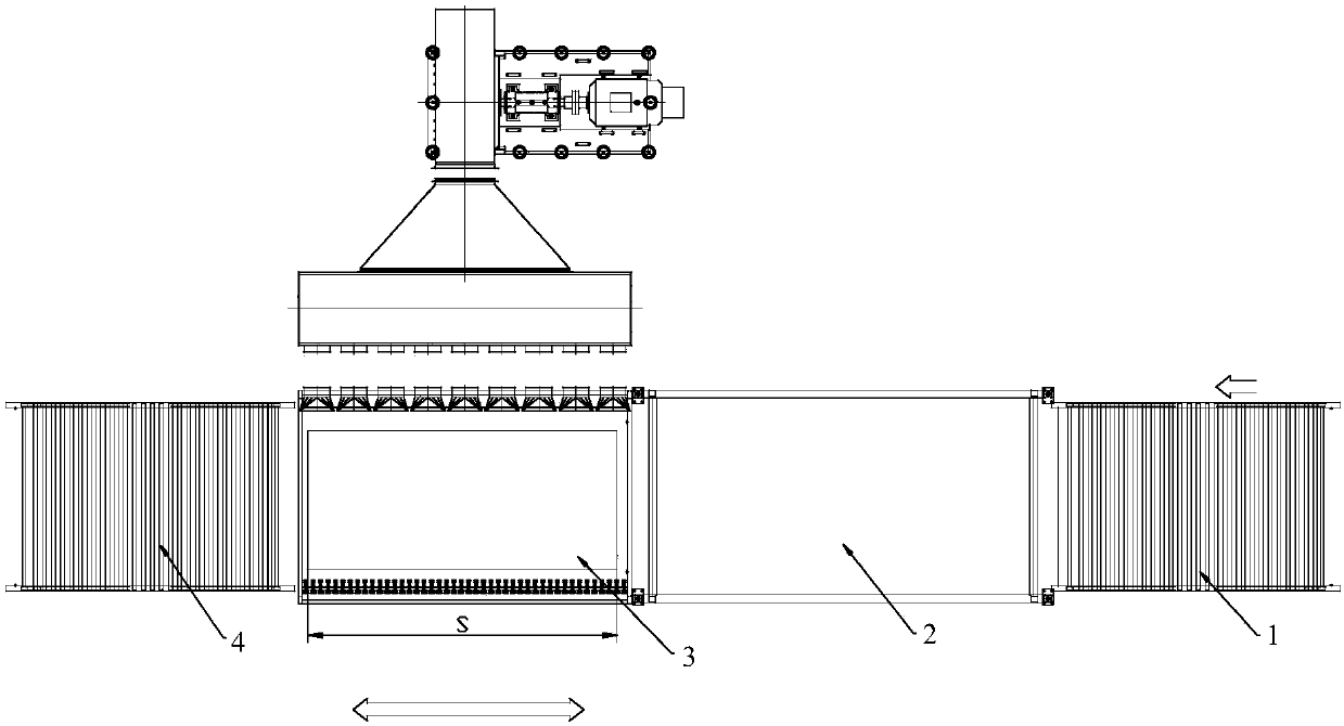
[0005] 1. In the first few seconds of the most critical formation of tempering, the conveying roller stops rotating (there will be a pause when the direction of rotation is switched), and then repeatedly stops at the same position. The cold glass cools slowly, resulting in uneven cooling of the glass and the formation of stress spots
[0006] 2. For the glass in the same furnace, the time from the time when the front glass comes out of the furnace to the first swing back is longer than the time from the back glass to the first swing back, which is S / V seconds longer, resulting in different heat dissipation from the front and back of the glass, and stress on the front and back of the glass. There is a difference

Method used


Image

  • Through type glass tempering furnace capable of effectively weakening tempering stress patterns
  • Through type glass tempering furnace capable of effectively weakening tempering stress patterns
  • Through type glass tempering furnace capable of effectively weakening tempering stress patterns

Examples


Embodiment Construction

[0043] Below in conjunction with each accompanying drawing, the present invention is described in detail.

[0044] Such as Figure 5As shown, a pass-through glass tempering furnace that can effectively weaken tempering stress spots includes a heating furnace 2, a scanning tempering device 5, and a cooling device 3 arranged in sequence. The scanning tempering device 5 is used to improve cooling efficiency. The glass in the heating furnace 2 is cooled in one pass, and the cooling device 3 is used for reciprocating cooling of the glass from the scanning tempering device 5 .

[0045] The "one-pass cooling" mentioned in this application refers to a one-time pass without pause and reciprocating movement, similar to a scanning operation; The glass will reciprocate in the cooling device 3; in this application, the cooling device 3 may be the cooling device 3 for reciprocating cooling in the prior art or background technology.

[0046] In the tempering process of tempered glass, the ...


PUM


Abstract

The invention discloses a through type glass tempering furnace capable of effectively weakening tempering stress patterns. The through type glass tempering furnace comprises a heating furnace, a scanning type tempering device and a cooling device which are sequentially arranged, wherein the scanning type tempering device is used for carrying out once-through type cooling on glass from the heatingfurnace, and the cooling device is used for carrying out reciprocating type cooling on the glass from the scanning type tempering device. In a tempering process of the tempered glass, the key is initial few seconds when tempering is formed, the scanning type tempering device is arranged between the cooling device and the heating furnace, and the once-through type cooling can be carried out on theglass from the heating furnace, so that defects in background art are overcome, and the situation that nonuniform heat dissipation is produced due to pause in the tempering process of the glass is eliminated; meanwhile, key T-second tempering is carried out, so that cooling efficiency is completely consistent from the beginning to the end, and the formation of the stress patterns of the tempered glass is effectively reduced.

Description

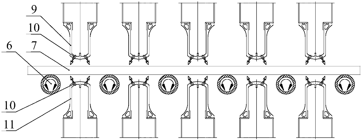
technical field [0001] The invention relates to tempered glass production equipment, in particular to a through-type glass tempering furnace capable of effectively weakening tempering stress spots. Background technique [0002] When tempered glass is broken, its fragments have rounded obtuse angles, no sharp edges and corners, and are not easy to hurt people. Therefore, tempered glass is widely used as doors and windows of automobiles, trains, ships, and buildings, and has a wide range of uses. The patent document with the publication number CN204281559U discloses a glass tempering furnace. The tempering glass processing flow is as follows: the glass is first heated in the heating furnace, then quickly removed from the heating furnace, and cooled by high-speed blowing. [0003] Such as figure 1 and 2 The existing glass tempering furnace shown includes a loading table 1, a heating furnace 2, a cooling device 3, and an unloading table 4 arranged in sequence. The glass 7 is h...

Claims


Application Information

Patent Timeline
Patent Type & Authority Applications(China)
IPC IPC(8): C03B27/012C03B35/00C03B27/044
CPCC03B27/012C03B27/044C03B35/00
Inventor 姚敏
Owner 杭州精工机械有限公司
Learn More