A high-voltage wire lead bracket

A technology of lead wire support and high-voltage line, which is applied in the direction of lifting devices, etc., can solve the problems of not being able to eliminate potential safety hazards of transformers, and not being able to realize high-altitude fast wiring operations for high-voltage line construction personnel, so as to achieve balanced working torque, increase overall rigidity, and increase work efficiency Effect

Inactive Publication Date: 2019-08-02
国网江西省电力有限公司九江供电分公司 +2
View PDF1 Cites 0 Cited by
  • Summary
  • Abstract
  • Description
  • Claims
  • Application Information

AI Technical Summary

Problems solved by technology

[0005] Aiming at the deficiencies in the existing technology, the purpose of the present invention is to provide a high-voltage wire lead bracket to solve the potential safety hazard of the transformer when the high-voltage wire lead bracket cannot climb up and down when working at heights, and cannot realize high-altitude fast wiring for high-voltage wire construction personnel. homework problem

Method used


Image

  • A high-voltage wire lead bracket
  • A high-voltage wire lead bracket
  • A high-voltage wire lead bracket

Examples


Embodiment Construction

[0030] In order to make the technical means, creative features, goals and effects achieved by the present invention easy to understand, the present invention will be further described below in conjunction with specific embodiments.

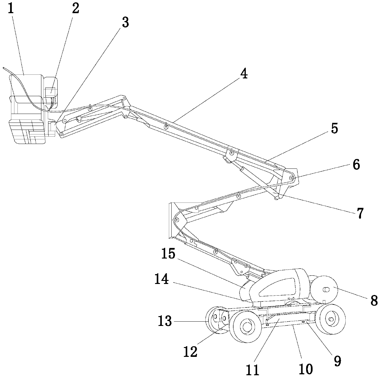
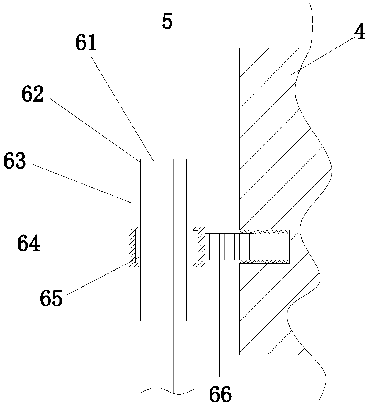
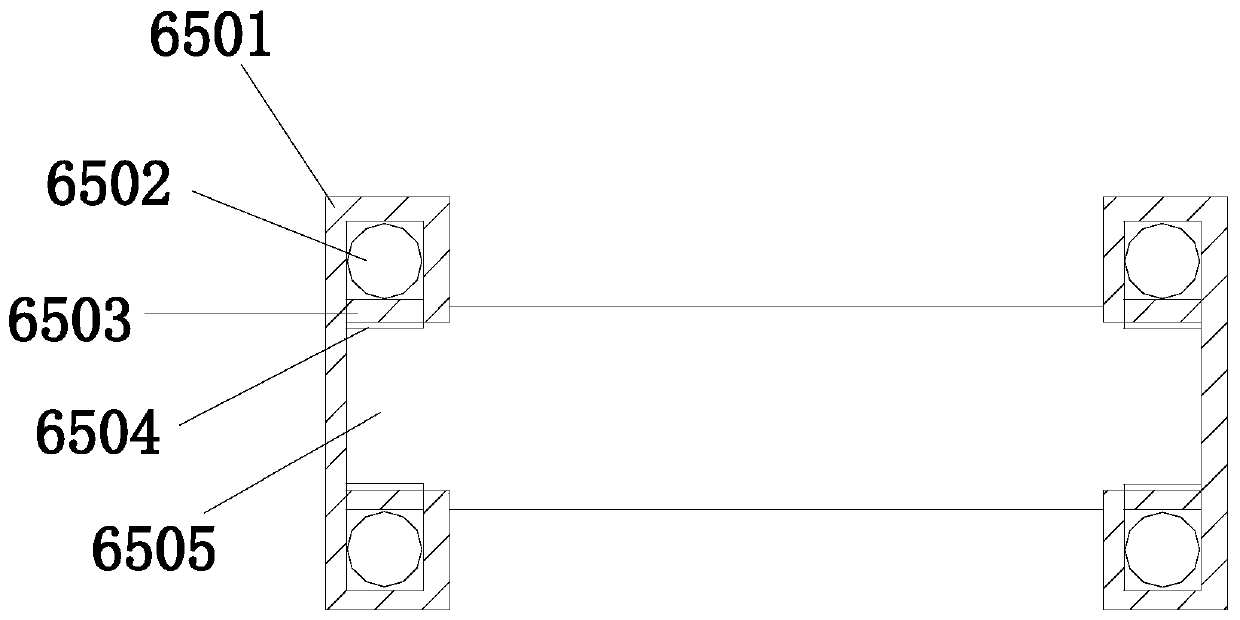
[0031] see Figure 1-Figure 8 , the present invention provides a high-voltage wire lead bracket, the structure of which includes a working platform 1, a controller 2, a three-dimensional rotating lifting joint 3, an arm frame 4, a high-voltage wire 5, a high-voltage wire guiding device 6, a hydraulic cylinder 7, a high-voltage wire drum 8, and a diesel engine 9. Self-propelled chassis 10, adjustable legs 11, traction support 12, driving wheel 13, turntable 14, drive control body 15; the front end of the self-propelled chassis 10 is provided with a traction support 12, and the traction The support 12 is welded to the self-propelled chassis 10, and the left and right sides of the self-propelled chassis 10 are evenly and equidistantly provided with fou...


PUM


Abstract

The invention discloses a novel high-voltage wire dragging support. The high-voltage wire dragging support structurally comprises an operation platform, a controller, a three-dimensional rotary lifting joint, an arm frame, a high-voltage wire, high-voltage wire guide devices, a hydraulic oil cylinder, a high-voltage wire roller, a diesel engine, a self-propelled chassis, an adjustable supporting leg, a traction support, driving wheels, a rotary table and a drive control machine body; and each high-voltage wire guide device comprises a groove, guide wheels, a high-voltage wire anti-falling support, bearing sleeves, guide wheel movable bearings and a screw rod. According to the high-voltage wire dragging support, the arm frame is arranged, the operation platform can be driven to ascend and descend through the cooperation of the hydraulic oil cylinder and the diesel engine so that potential safety hazards generated when constructors climb up and down to a transformer can be avoided, the high-voltage wire guide devices are arranged on the outer wall of the arm frame at equal intervals, the guide wheels and the high-voltage wire roller are coordinated with each other so as to quickly drag the high-voltage wire to the operation platform, the constructors can do the wiring job conveniently, working efficiency is improved, and overall safety of work is improved.

Description

technical field [0001] The invention relates to a high-voltage wire lead bracket, which belongs to the technical field of electric equipment. Background technique [0002] The power system is composed of power plants, transmission lines, substations, power distribution systems and loads. It is one of the most important and complex engineering systems in modern society. Among them, the substation is the core hub of the power grid and the "heart" of the power grid. During the maintenance of substation test equipment, such as measuring the dielectric loss of current transformers and voltage transformers, and the leakage current of lightning arresters, etc., at least 4 people are required to operate (1 person for wiring, 1 person for ladder, 1 person for ground operation, 1 person monitoring), and need to climb to transformers and other equipment, and some equipment cannot be attached to seat belts, which may easily cause high fall or close to 10kV equipment at high altitude an...

Claims


Application Information

Patent Timeline
Patent Type & Authority Patents(China)
IPC IPC(8): B66F11/04
CPCB66F11/044
Inventor 方晓妹刘存哲李长朝
Owner 国网江西省电力有限公司九江供电分公司
Why Eureka
Try Eureka