A winding machine and winding method for double-outer enameled wire outlets of a motor

A winding method and enameled wire technology, which are applied in the field of double outer enameled wire outlet winding machines and winding fields of motors, can solve the problems of reducing the overall height of the motor, poor and disadvantageous electromagnetic performance of the motor, and avoid disassembly and reassembly. The effect of being scratched and improving work efficiency

Active Publication Date: 2019-06-25
德州金力特电机有限公司
View PDF3 Cites 0 Cited by
  • Summary
  • Abstract
  • Description
  • Claims
  • Application Information

AI Technical Summary

Problems solved by technology

[0002] The stator coil is a very important part of the motor. The existing coils are usually wound from left to right in turn, and the winding method is formed at one time. The formed coil is as attached Figure 8 As shown, the incoming wire head is located in the axial direction of the end of the coil, and the outgoing wire head is located in the radial direction of the circumference of the coil. This kind of coil structure makes the coil install in the process of installing radially or axially. The end of the wire at the end of the coil always occupies the winding height of a turn of enameled wire, which causes a waste of installation space, is not conducive to reducing the overall height of the motor, and will also have a negative impact on the electromagnetic performance of the motor

Method used


Image

  • A winding machine and winding method for double-outer enameled wire outlets of a motor
  • A winding machine and winding method for double-outer enameled wire outlets of a motor
  • A winding machine and winding method for double-outer enameled wire outlets of a motor

Examples


no. 1 example

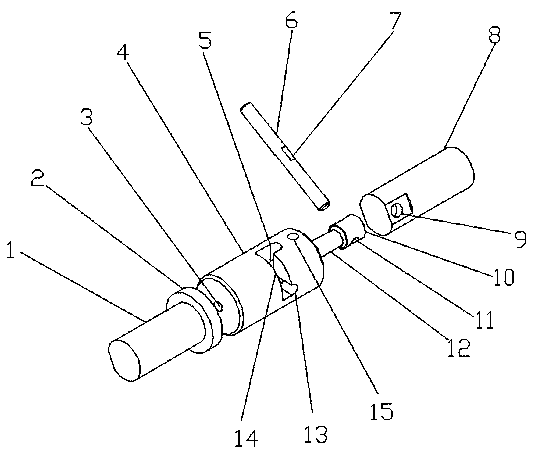
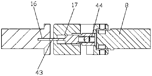
[0026] As a first embodiment of the present invention, the depth of the sleeve guide groove 17 is equal to the length of the mandrel guide shaft 12 .

[0027] As a second embodiment of the present invention, the depth of the sleeve guide groove 17 is greater than the length of the mandrel guide shaft 12 .

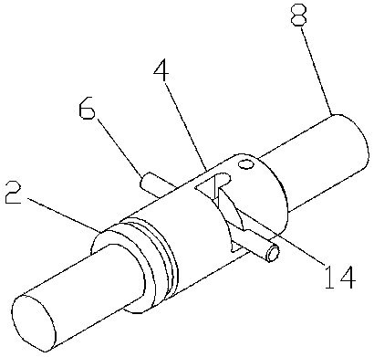
[0028] As a first embodiment of the present invention, a positioning groove 7 is processed in the middle of the rod body of the rotating rod 6, and the positioning groove 7 is a plane groove.

[0029] As a second embodiment of the present invention, a counterbore is processed in the middle of the rod body of the rotating rod 6 .

[0030] As a first embodiment of the present invention, the winding core on the mandrel 10 is cylindrical.

[0031] As a second embodiment of the present invention, the winding core on the mandrel 10 is square.

[0032] The length of the core removal groove 5 is equal to the length that the mandrel 10 protrudes from the core hole 3 , and the leng...


PUM


Abstract

The invention relates to a winding machine and a winding method for winding the outgoing wire of the double-outer-side enameled wire of a motor and belongs to the technical field of motor manufacturing. The mechanism is mainly designed with a split type winding core mechanism. When the winding is started, the length of a copper wire for one turn of a coil is reserved firstly. After that, a wire iswound on a winding core from left to right from the second turn, until the wire is wound by a preset number of turns. After that, the wire is wound from the right to the left. Repeated in this way, the wire is wound by a required number of layers. At this time, a handle is held to drive a sleeve to move backwards in the axis direction. Due to the fact that the position of a displacement groove islong, the distance between a left rotating shaft and the sleeve is increased by the length of one turn of the coil when a screw in a first positioning hole moves from a limit position at one side toa limit position at the other side. At this time, a main motor continues to rotate, and the first turn of a second coil is wound up. During the working process, two stations are arranged for the winding core, namely a locking station and a winding core withdrawal station, respectively. When the winding is completed, the winding core is enabled to rotate in the sleeve and retreat to the winding core withdrawal station. After that, the winding core exists from the coil.

Description

technical field [0001] The invention relates to the technical field of motor manufacturing, in particular to a winding machine and a winding method for double-outside enameled wire outlets of a motor. Background technique [0002] The stator coil is a very important part of the motor. The existing coils are usually wound from left to right in turn, and the winding method is formed at one time. The formed coil is as attached Figure 8 As shown, the incoming wire head is located in the axial direction of the end of the coil, and the outgoing wire head is located in the radial direction of the circumference of the coil. This kind of coil structure makes the coil install in the process of installing radially or axially. The wire ends at the end of the coil always occupy the winding height of one turn of enameled wire, which causes a waste of installation space, is not conducive to reducing the overall height of the motor, and also has a negative impact on the electromagnetic perf...

Claims


Application Information

Patent Timeline
Patent Type & Authority Patents(China)
IPC IPC(8): H02K15/04
CPCH02K15/0442
Inventor 董艺
Owner 德州金力特电机有限公司
Why Eureka
Try Eureka