
Vacuum liquid-cooled coupling heat management system of power battery and operating method

A power battery and management system technology, applied in the direction of secondary batteries, battery components, circuits, etc., can solve the problems of occupying the battery system, energy waste, and reducing the battery life of the power battery system, so as to improve battery life and life, The effect of reducing energy waste

Inactive Publication Date: 2018-02-16
DONGGUAN DRN NEW ENERGY
View PDF4 Cites 8 Cited by
  • Summary
  • Abstract
  • Description
  • Claims
  • Application Information

AI Technical Summary

Problems solved by technology

[0002] In the liquid heat management system currently used on the market, the liquid pipe is completely or evenly penetrated and covered with the battery cell (battery pack) in the application, making it into one or more circuits, and the heat is transferred to each other in the circuit to achieve the whole The temperature of the battery system is balanced. However, in this type of thermal management system, whether it is heating in a low-temperature environment, cooling in a high-temperature environment, or at a temperature suitable for the normal operation of the battery cell, the liquid in the pipeline is working, Occupying the resources of the battery system at any time, causing unnecessary waste of energy and reducing the battery life of the power battery system

Method used


Image

  • Vacuum liquid-cooled coupling heat management system of power battery and operating method

Examples


Embodiment Construction

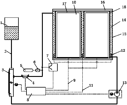
[0022] Refer to attached figure 1 The specific implementation manner of the present invention is introduced.

[0023] Such as figure 1 As shown, a vacuum liquid cooling coupled thermal management system for a power battery includes a battery pack 17, a hollow cooling plate 15 arranged on both sides of the battery pack 17, and a liquid cooling circuit 2 with a hydraulic pump 13 communicating with the cooling plate 15 And the battery control unit 8; the liquid cooling circuit 2 is connected with a temperature controller 3, a solenoid valve 4, a ventilator and a vacuum pump 7, the temperature controller 3 is connected with a coolant backup tank 1, and the ventilator includes a storage tank with a filter screen The air tank 5 and the intake valve 6 connected to the liquid cooling circuit 2; the temperature controller 3 is provided with a motor.

[0024] The front and rear ends of the battery pack 17 are provided with metal vacuum-type fixed end plates 16 for fixing the battery p...


PUM


Abstract

The invention discloses a vacuum liquid-cooled coupling heat management system of a power battery and an operating method. The vacuum liquid-cooled coupling heat management system comprises a batterypack, hollow cooling plates arranged on two sides of the battery pack, a liquid cooling circuit, with a hydraulic pump, communicating with the cooling plates, and a battery control unit, wherein the liquid cooling circuit is connected with a temperature controller, an electromagnetic valve, an air interchanger and a vacuum pump; the temperature controller is connected with a cooling liquid standbytank; and the air interchanger comprises an air storage tank with a filter screen and an air inlet valve connected with the liquid cooling circuit. The temperature conduction between battery packs isisolated by vacuum plates formed by the cooling plates through the air interchanger and a vacuum pump system, the effects of heat insulation and heat preservation are reached, the hidden danger thatthe temperature of the dense region of the battery pack is increased locally is solved, and the waste of energy sources is reduced, so that the cruising power of a finished automobile power battery system is improved, and the service life of the finished automobile power battery system is prolonged; and when the local temperature is abnormal, liquid can be quickly filled for cooling, so that the temperature of the battery pack and the temperature of the finished automobile system are balanced again.

Description

technical field [0001] The invention relates to the field of batteries, in particular to a vacuum liquid cooling coupled thermal management system and working method of a power battery. Background technique [0002] In the liquid heat management system currently used on the market, the liquid pipe is completely or uniformly penetrated and covered with the battery cell (battery pack) in the application, making it into one or more circuits, and the heat is transferred to each other in the circuit to achieve the whole The temperature of the battery system is balanced. However, in this type of thermal management system, whether it is heating in a low-temperature environment, cooling in a high-temperature environment, or at a temperature suitable for the normal operation of the battery cell, the liquid in the pipeline is working, The resources of the battery system are occupied at any time, causing unnecessary waste of energy and reducing the battery life of the power battery sys...

Claims


Application Information

Patent Timeline
Patent Type & Authority Applications(China)
IPC IPC(8): H01M10/613H01M10/615H01M10/625H01M10/635H01M10/6554H01M10/6555H01M10/6557H01M10/6567H01M10/658H01M2/10H01M50/204
CPCH01M10/613H01M10/615H01M10/625H01M10/635H01M10/6554H01M10/6555H01M10/6557H01M10/6567H01M10/658H01M50/20Y02E60/10
Inventor 刘厚德李帅光饶华兵
Owner DONGGUAN DRN NEW ENERGY
Learn More