Homemade foundation laser radar alignment error-based point cloud error correction method

A laser radar and alignment error technology, which is applied in the field of point cloud error correction based on self-made ground-based laser radar alignment error, can solve problems such as theoretical analysis and system error model parameters without physical meaning

Active Publication Date: 2018-02-16
BEIHANG UNIV
View PDF7 Cites 29 Cited by
  • Summary
  • Abstract
  • Description
  • Claims
  • Application Information

AI Technical Summary

Problems solved by technology

This type of method obtains a system error correction model for all three-dimensional coordinate measurement systems. Its disadvantage is that the parameters of the system error model have no physical meaning, and it does not conduct theoretical analysis on the scanning mode of the system itself from the perspective of error sources. Therefore, it relies on large sample data to achieve Accurate correction; the above-mentioned patents include "a correction method for long-distance scanning laser radar measurement error" disclosed in Chinese patent 201710014687.8

Method used


Image

  • Homemade foundation laser radar alignment error-based point cloud error correction method
  • Homemade foundation laser radar alignment error-based point cloud error correction method
  • Homemade foundation laser radar alignment error-based point cloud error correction method

Examples


Embodiment Construction

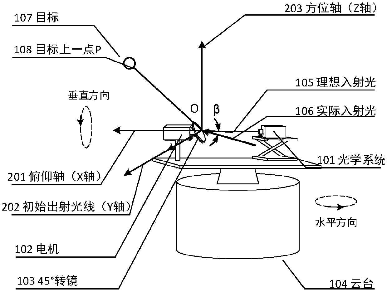
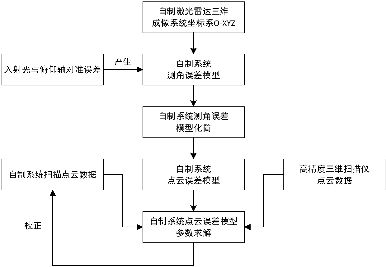
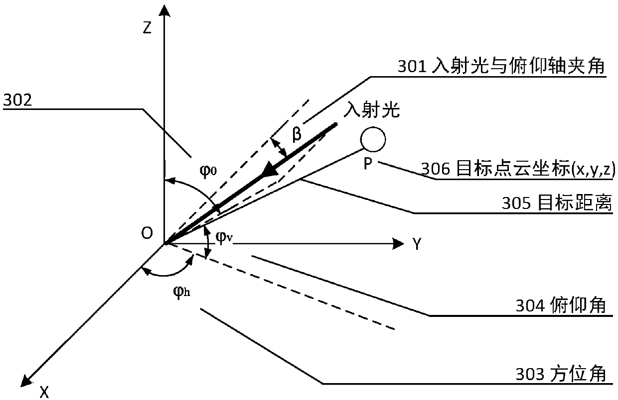
[0063] The specific implementation manner of the patent of the present invention will be further described in detail below in conjunction with the accompanying drawings. Schematic diagram of the point cloud error correction method based on self-made ground-based lidar alignment error. figure 2 As shown, first establish the coordinate system O-XYZ of the self-made lidar three-dimensional imaging system (713), because there is an alignment error between the actual incident light (106) and the pitch axis X-axis (201) in the self-made system (301, 302), the alignment error is theoretically derived in the coordinate system of the self-made lidar 3D imaging system (713) (301, 302) For the influence of the angle measurement error of the self-made laser radar three-dimensional imaging system (713), an angle measurement error model of the self-made laser radar three-dimensional imaging system (713) is obtained. According to the principle of trigonometric function approximation, the...


PUM


Abstract

The present invention discloses a homemade foundation laser radar alignment error-based point cloud error correction method. The method mainly aims at a scanning mode that a 45-degree rotating mirrorof a homemade laser radar system cooperates with a pan-tilt to rotate, establishes a homemade laser radar system point cloud error correction model by calculating the influence of an alignment error between the incident light and a pitch axis on a homemade system angle measurement error, and adopts the scanned point cloud coordinate of a high-precision three-dimensional scanner to a target as a real value solution alignment error, so that the error correction of the homemade laser radar system alignment error to the target point cloud is realized. The method mainly comprises the following three steps of 1) establishing and simplifying a homemade laser radar three-dimensional imaging system angle measurement error model caused by the alignment error; 2) obtaining a homemade laser radar three-dimensional imaging system point cloud error model; 3) solving the alignment error in the homemade laser radar three-dimensional imaging system point cloud error model, and correcting the homemade laser radar system target point cloud according to the model.

Description

technical field [0001] The invention relates to the technical field of laser radar measurement, in particular to a point cloud error correction method based on self-made ground-based laser radar alignment error Background technique [0002] Lidar measurement technology is a new active remote sensing technology that has developed rapidly in recent years. It generally uses non-contact measurement technology and has a wide range of applications in remote sensing, military detection, oceanographic mapping, and atmospheric exploration. Based on the traditional single-point measurement technology, the three-dimensional scanning measurement technology in LiDAR can quickly obtain high-resolution point cloud data on the surface of the target object through high-speed laser scanning. This technology has the advantages of simple data processing, rapidity, It has the advantages of initiative, strong anti-interference ability, high measurement accuracy and large range. However, the scan...

Claims


Application Information

Patent Timeline
IPC IPC(8): G01S7/497G01S17/42
CPCG01S7/497G01S17/42
Inventor 李小路徐立军李昀晔谢鑫浩
Owner BEIHANG UNIV
Why Eureka
Try Eureka