An extractant dilution device for rare earth extraction

A dilution device and extraction agent technology, applied in the field of dilution devices for rare earth extraction, can solve the problems of low dilution efficiency, reduced rare earth extraction efficiency, time-consuming and labor-intensive problems, and achieve the effect of improving dilution efficiency

Active Publication Date: 2019-08-20
业达检测有限公司
View PDF7 Cites 0 Cited by
  • Summary
  • Abstract
  • Description
  • Claims
  • Application Information

AI Technical Summary

Problems solved by technology

[0005] In order to overcome the shortcomings of manually stirring the extractant and kerosene to mix the extractant and kerosene to achieve the purpose of diluting the extractant, the present invention is time-consuming, laborious, low in dilution efficiency, and will reduce the efficiency of rare earth extraction. The technical problem to be solved by the present invention It is to provide an extraction agent dilution device for rare earth extraction that can save time and labor, improve the dilution efficiency of the extraction agent, and improve the extraction efficiency of rare earths.

Method used


Image

  • An extractant dilution device for rare earth extraction
  • An extractant dilution device for rare earth extraction
  • An extractant dilution device for rare earth extraction

Examples


Embodiment 1

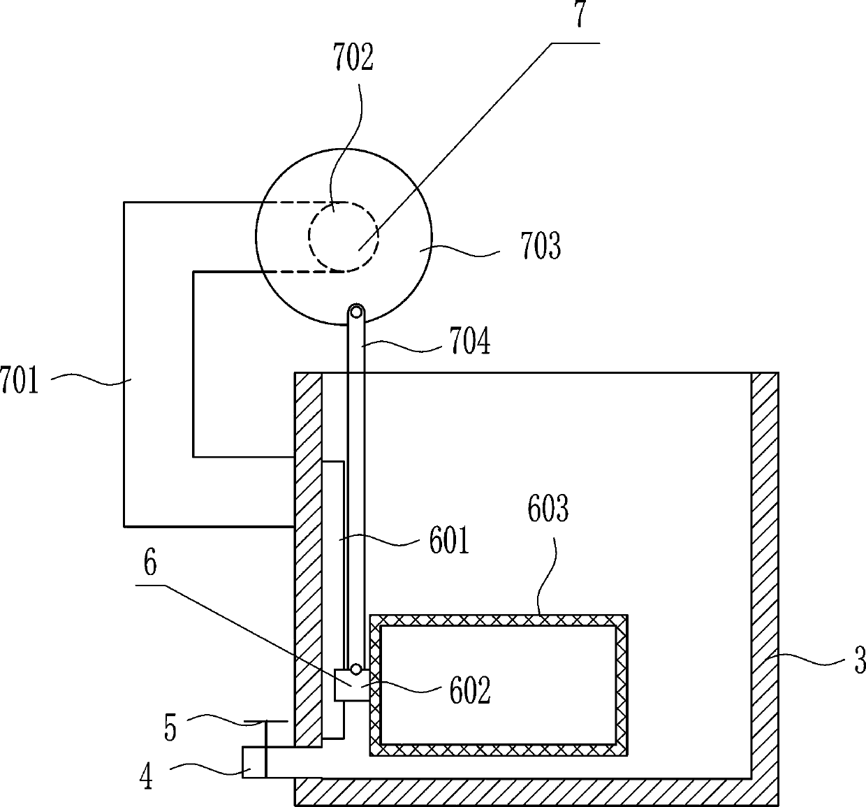
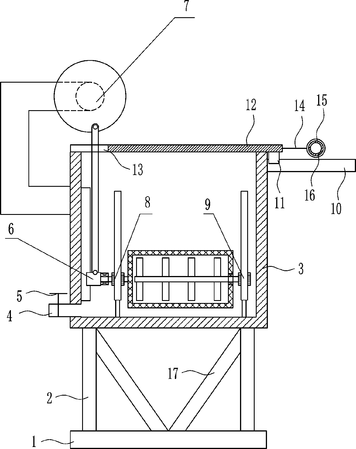
[0037] An extractant dilution device for rare earth extraction, such as Figure 1-7 As shown, it includes a base 1, a support rod 2, a stirring tank 3, a liquid outlet pipe 4, a valve 5, a first stirring device 6 and a driving device 7, and the left and right sides of the top of the base 1 are vertically connected with a support rod by bolts. 2. A stirring box 3 is connected by bolts between the tops of the two struts 2, and a liquid outlet pipe 4 is connected to the lower left side of the stirring box 3, and a valve 5 is arranged on the liquid outlet pipe 4, and a second valve 5 is installed in the stirring box 3 A stirring device 6, a driving device 7 is arranged on the upper left side of the stirring box 3.

Embodiment 2

[0039] An extractant dilution device for rare earth extraction, such as Figure 1-7 As shown, it includes a base 1, a support rod 2, a stirring tank 3, a liquid outlet pipe 4, a valve 5, a first stirring device 6 and a driving device 7, and the left and right sides of the top of the base 1 are vertically connected with a support rod by bolts. 2. A stirring box 3 is connected by bolts between the tops of the two struts 2, and a liquid outlet pipe 4 is connected to the lower left side of the stirring box 3, and a valve 5 is arranged on the liquid outlet pipe 4, and a second valve 5 is installed in the stirring box 3 A stirring device 6, a driving device 7 is arranged on the upper left side of the stirring box 3.

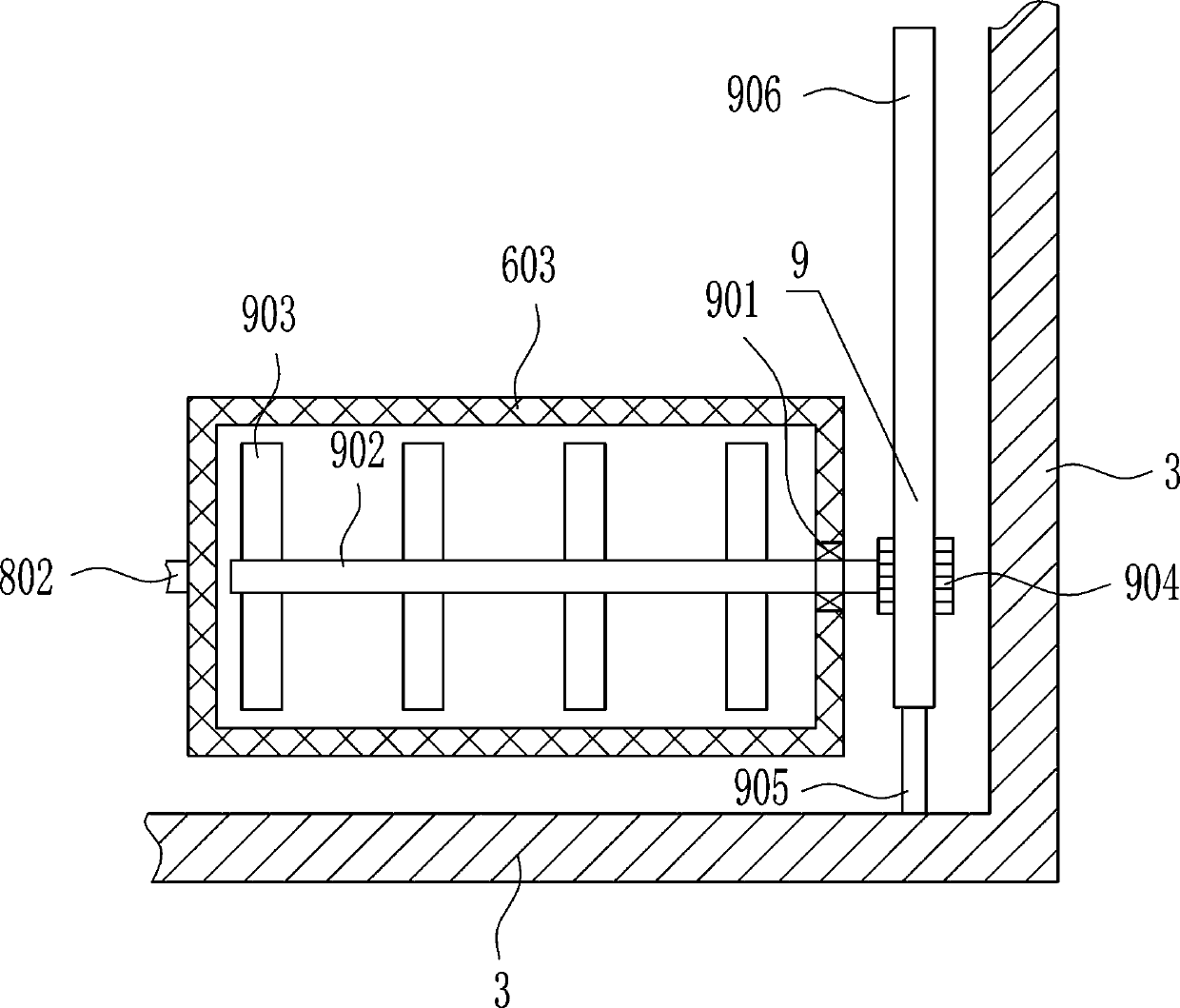
[0040] The first stirring device 6 includes the first slide rail 601, the first slide block 602 and the screen frame 603, the left side of the first slide rail 601 is connected with the left side in the mixing box 3 by bolts, on the first slide rail 601 There is a fir...

Embodiment 3

[0042] An extractant dilution device for rare earth extraction, such as Figure 1-7 As shown, it includes a base 1, a support rod 2, a stirring tank 3, a liquid outlet pipe 4, a valve 5, a first stirring device 6 and a driving device 7, and the left and right sides of the top of the base 1 are vertically connected with a support rod by bolts. 2. A stirring box 3 is connected by bolts between the tops of the two struts 2, and a liquid outlet pipe 4 is connected to the lower left side of the stirring box 3, and a valve 5 is arranged on the liquid outlet pipe 4, and a second valve 5 is installed in the stirring box 3 A stirring device 6, a driving device 7 is arranged on the upper left side of the stirring box 3.

[0043] The first stirring device 6 includes the first slide rail 601, the first slide block 602 and the screen frame 603, the left side of the first slide rail 601 is connected with the left side in the mixing box 3 by bolts, on the first slide rail 601 There is a fir...


PUM


Abstract

The invention relates to a dilution device for rare earth extraction, in particular to an extractant dilution device for rare earth extraction. The technical problem to be solved by the present invention is to provide an extraction agent dilution device for rare earth extraction that can save time and effort, improve the dilution efficiency of the extraction agent, and improve the extraction efficiency of rare earths. In order to solve the above-mentioned technical problems, the present invention provides such an extraction agent dilution device for rare earth extraction, which includes a base, etc.; the left and right sides of the top of the base are vertically connected with support rods through bolts, and the top ends of the two support rods A stirring box is connected by bolts, a liquid outlet pipe is connected to the lower left side of the stirring box, a valve is arranged on the liquid outlet pipe, and a first stirring device is arranged in the stirring box. The present invention can drive the first stirring device to stir the extractant and kerosene through the driving device, and can quickly dilute the extractant, thereby achieving the effects of saving time and labor, improving the dilution efficiency of the extractant, and improving the extraction efficiency of rare earths.

Description

technical field [0001] The invention relates to a dilution device for rare earth extraction, in particular to an extractant dilution device for rare earth extraction. Background technique [0002] Rare earths are known as "industrial vitamins". Now it has become an extremely important strategic resource. Rare earth element oxides refer to oxides of 15 lanthanide elements with atomic numbers from 57 to 71 in the periodic table of elements, and oxides of scandium and yttrium, a total of 17 elements whose chemical properties are similar to lanthanide elements. [0003] Before using the extractant to extract the rare earth, it is necessary to dilute the extractant with kerosene and other solvents before use. At present, the extractant and kerosene are generally stirred manually to mix the extractant and kerosene to achieve the purpose of diluting the extractant, which is time-consuming and laborious. The dilution efficiency is low, which will reduce the efficiency of rare eart...

Claims


Application Information

Patent Timeline
Patent Type & Authority Patents(China)
IPC IPC(8): C22B59/00C22B3/02C22B3/26
CPCC22B3/02C22B59/00C22B3/26Y02P10/20
Inventor 曾龙章仕磊
Owner 业达检测有限公司
Why Eureka
Try Eureka