Fault indicator

A technology of fault indicator and casing, which is applied in the direction of fault location, fault detection according to conductor type, measuring device casing, etc. It can solve the problem that it is difficult to observe whether the indicator light is on or not, it is easily disturbed by rain and snow, and the indicator light is not large and other problems, to achieve the effect of improving the fault detection speed, saving manpower and material resources, and being easy to use

Active Publication Date: 2018-02-13
WUHU KAIXIN ARRESTER
View PDF14 Cites 2 Cited by
  • Summary
  • Abstract
  • Description
  • Claims
  • Application Information

AI Technical Summary

Problems solved by technology

[0003] When the traditional fault indicator is put into use, it is detected by the indicator light of the fault indicator. Since the indicator light is not large in size and is also affected by location factors, it is also easily disturbed by rain and snow. It is difficult to observe whether the indicator light is When it is turned on, inspectors need to go to the scene to check the indication of the indicator, which wastes a lot of manpower and material resources and brings great difficulties to the inspection work.

Method used


Image

  • Fault indicator
  • Fault indicator
  • Fault indicator

Examples


Embodiment Construction

[0022] Through the description of the embodiments below, the specific implementation of the present invention includes the shape, structure, mutual position and connection relationship between the various parts, the function and working principle of each part, the manufacturing process and the operation and use method of the various components involved. etc., to make further detailed descriptions to help those skilled in the art have a more complete, accurate and in-depth understanding of the inventive concepts and technical solutions of the present invention.

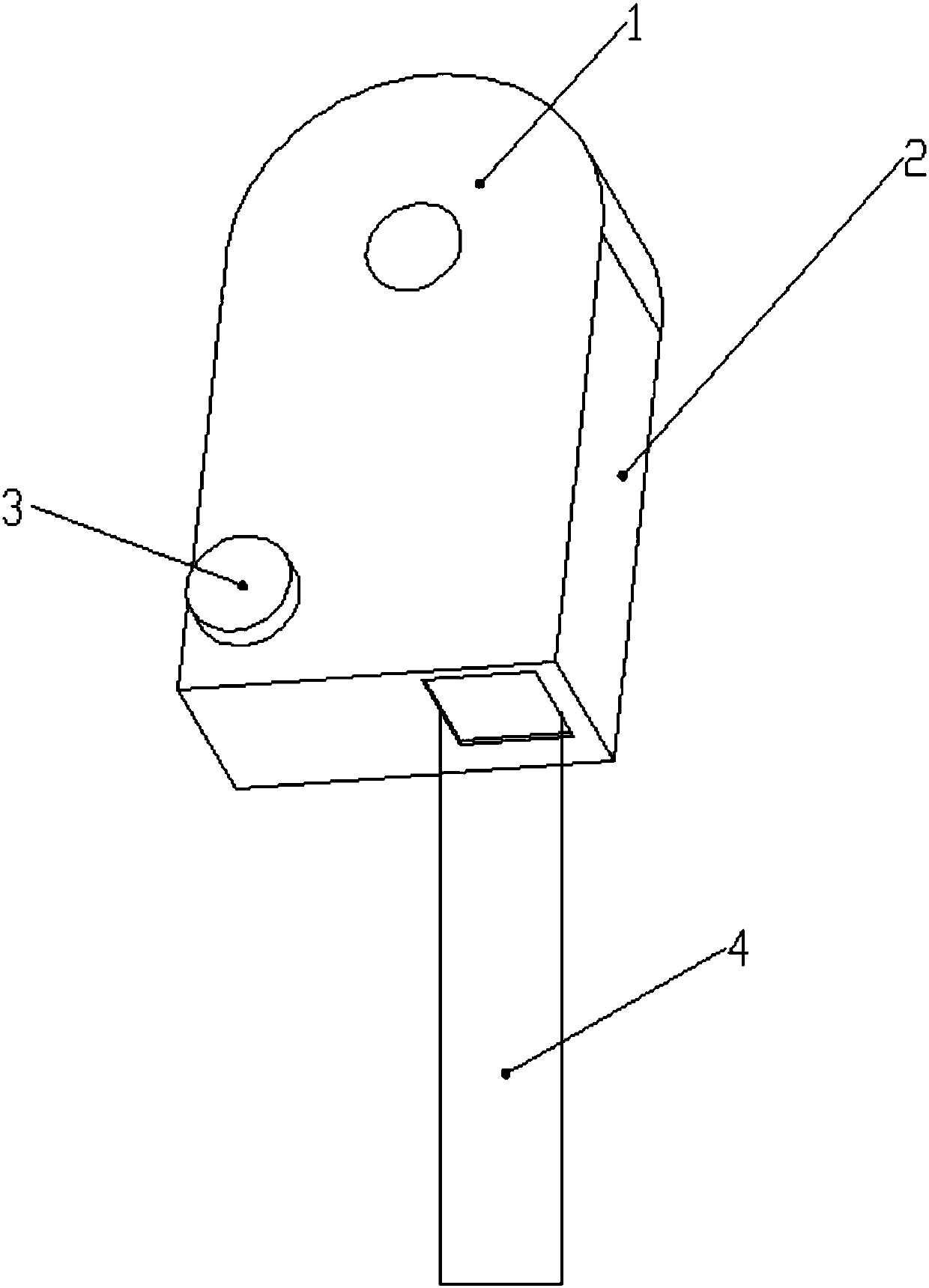
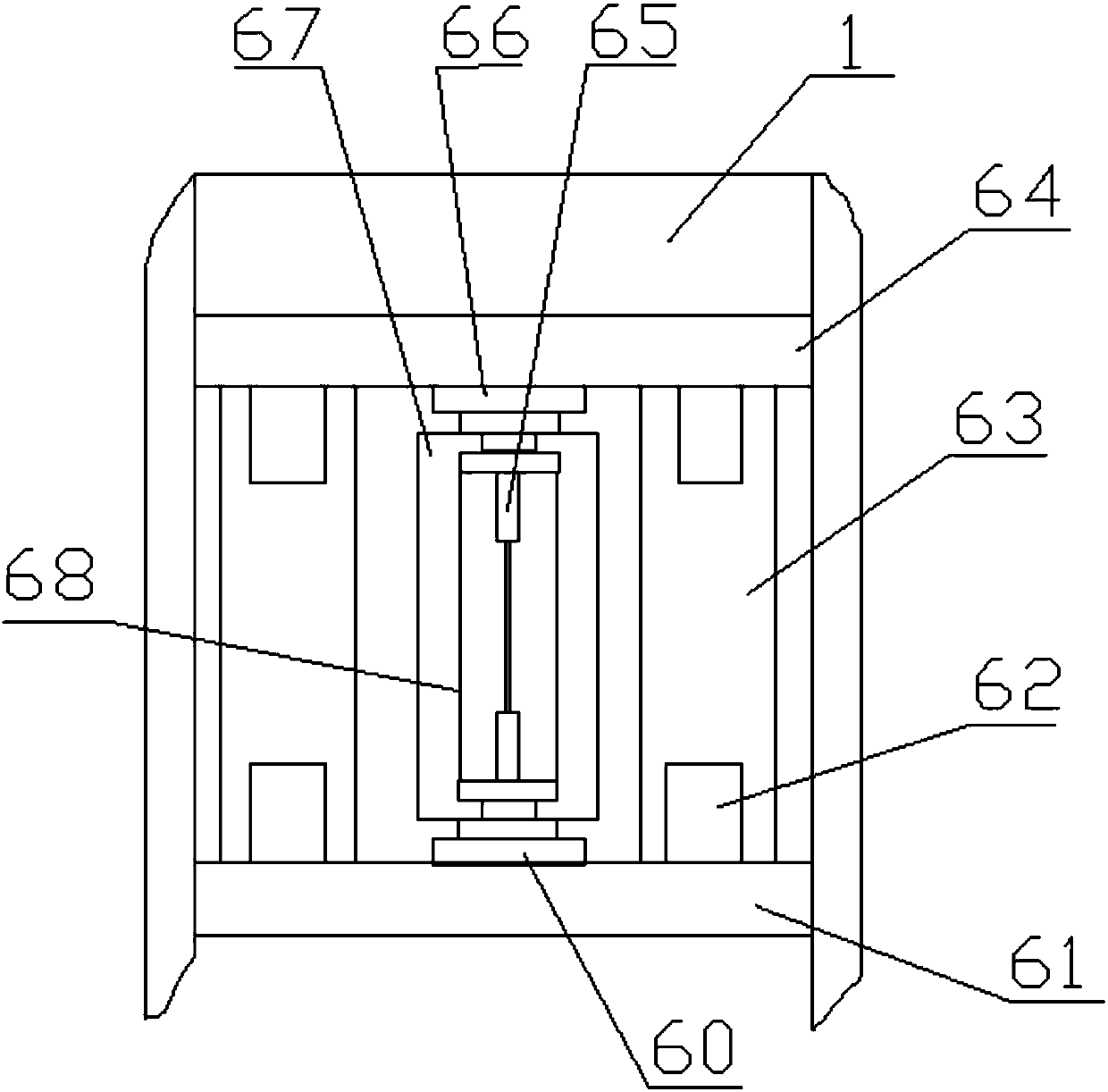
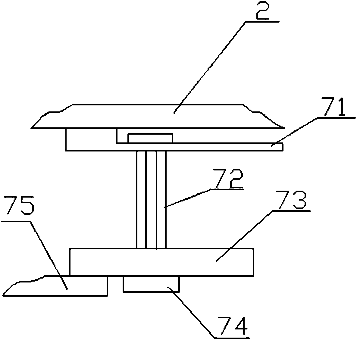
[0023] Such as Figure 1 to Figure 4 As shown, a fault indicator includes a lower casing 1, an upper casing 2, a battery box 3, a colored ribbon 4, a spring device 5, an electronically controlled thermal squib device 6, a shock absorbing device 7, and a plastic sheet 8.

[0024] The battery box is directly placed on the battery installation inside the lower casing 1, the spring device 5 is installed inside the lower ca...


PUM


Abstract

The invention discloses a fault indicator. The fault indicator comprises an upper machine casing, a lower machine casing, a plastic thin sheet, an electric control thermal explosion pipe device, a spring device and a vibration absorption device, wherein the plastic thin sheet is embedded into the lower left end of the lower machine casing; the electric control thermal explosion pipe device and thespring device are mounted in the lower machine casing; the vibration absorption device is mounted in the upper machine casing; when a circuit system has faults and the electric control thermal explosion pipe device is exploded, a colored ribbon and the spring device are pushed to move upward; meanwhile, the plastic thin sheet is extruded and the spring device regains the elasticity to push out the colored ribbon downward, so that the working of the fault indicator is realized, the working intensity of detectors is reduced and the manpower and material resources are saved.

Description

technical field [0001] The invention relates to the technical field of power grid line detection equipment, in particular to a fault indicator. Background technique [0002] In the power grid system, the circuit situation is complicated, and there are branches of various lines. Once the circuit in a certain place fails, engineers need a lot of time to check the circuit, especially in remote mountainous areas, where the geographical form is complex and the inspection work is very difficult. With the With the advancement of science and technology, indicators have been widely used as a technical means of fault location. [0003] When the traditional fault indicator is put into use, it is detected by the indicator light of the fault indicator. Since the indicator light is not large in size and is also affected by location factors, it is also easily disturbed by rain and snow. It is difficult to observe whether the indicator light is When it is turned on, inspectors need to go t...

Claims


Application Information

Patent Timeline
Patent Type & Authority Applications(China)
IPC IPC(8): G01R1/04G01R31/08
CPCG01R1/04G01R31/085
Inventor 陈波
Owner WUHU KAIXIN ARRESTER
Why Eureka
Try Eureka