Lead wire arrangement structure capable of controlling direct current resistance unbalance

A technology of DC resistance and layout structure, applied in the field of transformers, can solve the problems of increasing material consumption and occupying space, increasing overall weight and volume, wasting space, etc., and achieving the effects of good control, improved operating performance and simple process

Pending Publication Date: 2018-02-09
SHANDONG DACHI ELECTRIC
View PDF0 Cites 0 Cited by
  • Summary
  • Abstract
  • Description
  • Claims
  • Application Information

AI Technical Summary

Problems solved by technology

[0002] In the existing technology, it is a common phenomenon that the resistance unbalance rate caused by low voltage and high current exceeds the national standard, and this problem has always troubled transformer manufacturers and users
[0003] At this stage, in order to ensure that the resistance unbalance rate reaches a reasonable value, it is necessary to increase the size of the low-voltage copper bar, thereby increasing material consumption and occupying space, increasing the overall weight and volume, which not only wastes materials, increases costs, but also wastes space

Method used


Image

  • Lead wire arrangement structure capable of controlling direct current resistance unbalance
  • Lead wire arrangement structure capable of controlling direct current resistance unbalance
  • Lead wire arrangement structure capable of controlling direct current resistance unbalance

Examples


Embodiment 1

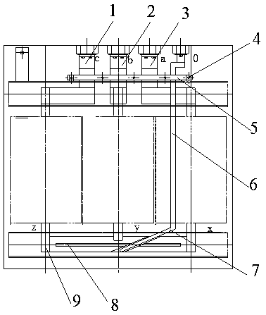
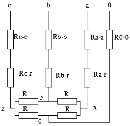
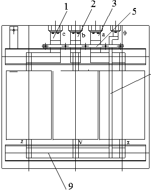
[0037] Such as figure 1 , figure 2 As shown, a lead arrangement structure for controlling DC resistance unbalance includes a head copper bar and a tail copper bar. The head copper bar includes a-phase copper bar 1, b-phase copper bar 2 and c-phase copper bar 3, and the tail The head copper bar is a low-voltage neutral point copper bar 9; a long strip-shaped notch 8 is set on the low-voltage neutral point copper bar 9, and the width of the notch 8 is greater than 8mm (if it is too narrow, it is easy to connect at the notch or leave solder ); the left end of the notch 8 does not reach the left end of the low-voltage neutral point copper bar 9, and the right end of the notch 8 does not reach the right end of the low-voltage neutral point copper bar 9.

[0038] Phase a line is drawn from phase a copper bar 1, and the end x of phase a line is welded to the left end of copper bar 9 of low-voltage neutral point; phase line b is drawn from phase b copper bar 2, and the end y of phas...


PUM

PropertyMeasurementUnit
widthaaaaaaaaaa

Abstract

The present invention discloses a lead wire arrangement structure capable of controlling direct current resistance unbalance, pertaining to the field of transformers. The structure comprises a head copper bar and a tail copper bar. The head copper bar comprises an A phase copper bar, a B phase copper bar and a C phase copper bar. The tail copper bar is a low-voltage neutral point copper bar. The low-voltage neutral point copper bar is provided with a slot. An A phase wire is led from the A phase copper bar, and a tail x of the A phase wire is connected to the left end of the low-voltage neutral point copper bar. A B phase wire is led from the B phase copper bar, and a tail y of the B phase wire is connected to the upper side of the slot. A C phase wire is led from the C phase copper bar, and a tail z of the C phase wire is connected to the right end of the low-voltage neutral point copper bar. A neutral point lead-out wire zero tail is connected to the lower side of the slot. Accordingto the structure, the direct current resistance unbalance can be well controlled. The structure has the advantages of simple process, easiness for operation, reduced cost, safety, reliability, nice appearance of line shape and improved transformer operation performance.

Description

technical field [0001] The invention relates to the field of transformers, in particular to a lead arrangement structure for controlling unbalanced DC resistance. Background technique [0002] In the prior art, it is a common phenomenon that the resistance unbalance rate caused by low voltage and high current exceeds the requirements of national standards, and this problem has always troubled transformer manufacturers and users. [0003] At this stage, in order to ensure that the resistance unbalance rate reaches a reasonable value, it is necessary to increase the size of the low-voltage copper bar, thereby increasing material consumption and occupying space, increasing the overall weight and volume, which not only wastes materials, increases costs, but also wastes space. [0004] It is an urgent problem to develop an effective solution to the DC resistance unbalance problem. Contents of the invention [0005] In order to make up for the deficiencies of the prior art, imp...

Claims


Application Information

Patent Timeline
Patent Type & Authority Applications(China)
IPC IPC(8): H01F27/29H01F27/28
CPCH01F27/28H01F27/29
Inventor 梁凤山李佳伟黄启锋蔡传峰
Owner SHANDONG DACHI ELECTRIC
Why Eureka
Try Eureka