Glass bulb with cathode-ray tube and cathode-ray tube

A technology for cathode ray tubes and glass bubbles, applied in the direction of cathode ray tubes/electron beam tubes, cathode ray/electron beam tube shells/containers, discharge tubes, etc., can solve the problem that excessive thermal stress cannot be generated and insufficient reduction The weight of the funnel part, reducing the strength of the funnel part, etc.

Inactive Publication Date: 2002-10-23
ASAHI GLASS CO LTD
View PDF2 Cites 4 Cited by
  • Summary
  • Abstract
  • Description
  • Claims
  • Application Information

AI Technical Summary

Problems solved by technology

During heat treatment, the funnel section is heated or cooled too quickly to create undue thermal stress, reducing the strength of the funnel section
In fact the weight of the funnel part was not sufficiently reduced as the funnel part was provided with a greater wall thickness in order to compensate for the reduced strength of the normal design

Method used


Image

  • Glass bulb with cathode-ray tube and cathode-ray tube
  • Glass bulb with cathode-ray tube and cathode-ray tube
  • Glass bulb with cathode-ray tube and cathode-ray tube

Examples


Embodiment Construction

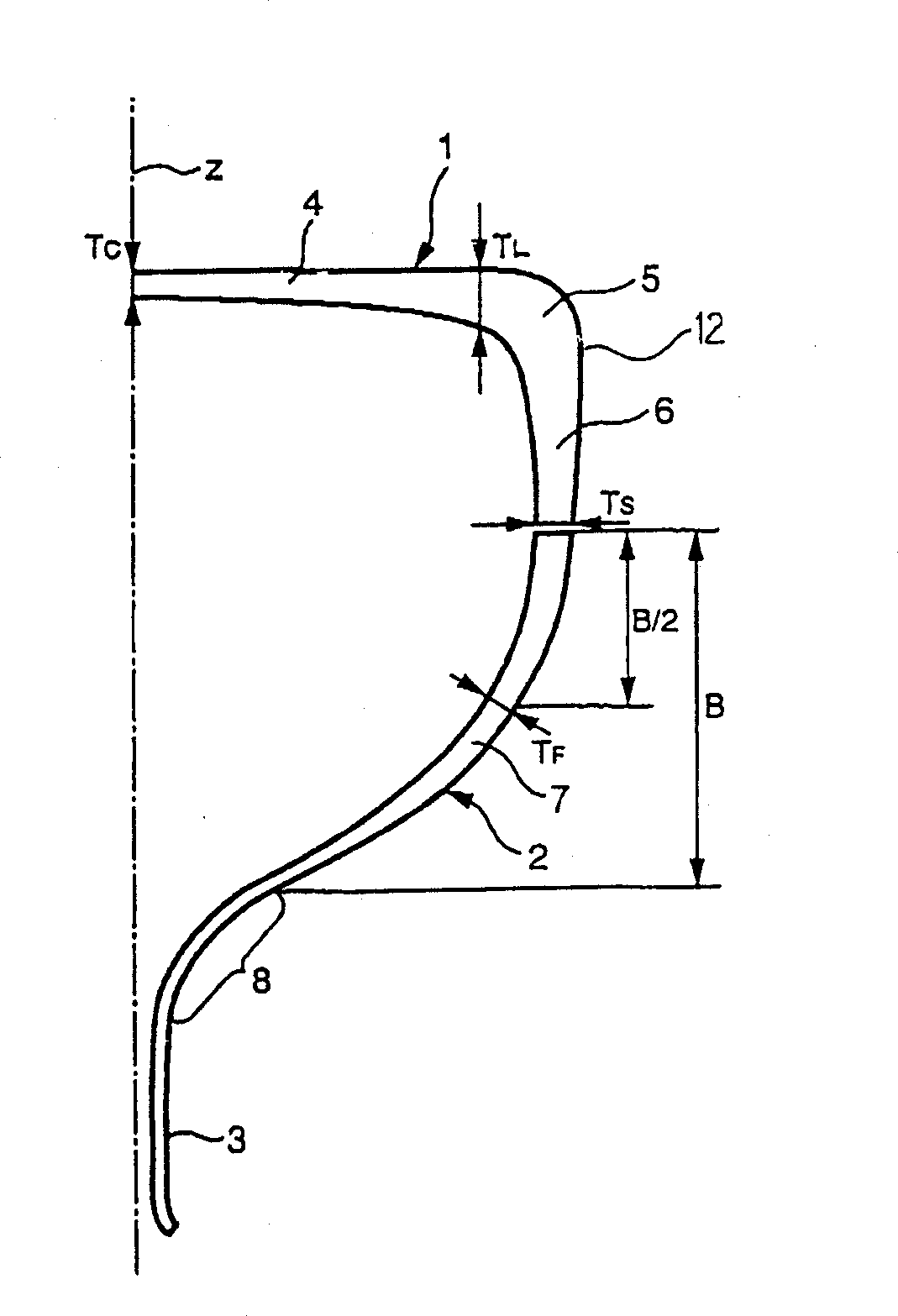
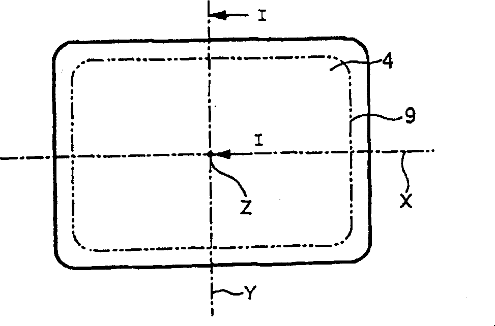
[0028] Now, the present invention will be specifically described with reference to the accompanying drawings. figure 1 is a partial sectional view of a glass bulb for a cathode ray tube of an embodiment of the present invention, figure 2 is a plan view of the panel portion; and figure 1 is along figure 2 A cross-sectional view taken along the line I-I. in other words, figure 1 The cross-sectional shape of the right half of the glass bubble taken along the short axis is shown. exist figure 2 In , the symbols X and Y denote the major axis and the minor axis of the surface part 4 respectively, and the dotted line 9 represents the useful screen area in the surface part 4 . In the glass bubble of this example, since the wall thickness of the end of the useful screen area in the surface portion 4 on the minor axis is greater than that of the end of the useful screen area on the major axis, the screen portion and funnel relative to the minor axis section fully defines the re...


PUM


Abstract

When the central wall thickness of the surface part (4) of the screen part (1) is TC, the wall thickness of the end part of the useful screen area is TL, the width of the sealing end face of the skirt part is TS, and the body of the funnel part (2) When the middle part of part (7) is TF, the following formulas can be established: TL / TC≥1.70, TS / TL=0.43-0.50 and TF / TC=0.37-0.49, apply 5-14 MPa to the side of the skirt part strengthened compressive stress.

Description

technical field [0001] The present invention relates to a glass bulb for a cathode ray tube and a cathode ray tube in which a surface portion has a substantially flat outer surface, the surface portion having a sharply varying wall thickness distribution. Background technique [0002] In a cathode ray tube, the housing includes a glass bulb including a panel portion for displaying an image, and a funnel portion in the shape of a funnel, one end of which is provided with a neck for housing an electron gun. the screen portion is substantially box-shaped and comprises a substantially rectangular surface portion providing a screen (screen area) and a skirt portion extending substantially perpendicularly from the periphery of the surface portion, to form a side wall. [0003] In recent years, there has been adopted a panel portion in which a surface portion has a substantially flat outer surface and a concave inner surface and is thermally reinforced to improve strength. Genera...

Claims


Application Information

Patent Timeline
IPC IPC(8): H01J29/02H01J29/86
CPCH01J29/861H01J29/02
Inventor 菅原恒彦清水直也村上敏英
Owner ASAHI GLASS CO LTD
Why Eureka
Try Eureka