High-speed spindle device provided with automatic balance mechanism
A high-speed spindle, self-balancing technology, applied in the direction of manufacturing tools, metal processing machinery parts, large fixed members, etc., can solve problems such as unfavorable long-term use of the spindle, spindle damage, etc., to achieve easy implementation, extended service life, and simple overall structure. Effect
- Summary
- Abstract
- Description
- Claims
- Application Information
AI Technical Summary
Problems solved by technology
Method used
Image

Examples
Embodiment 1
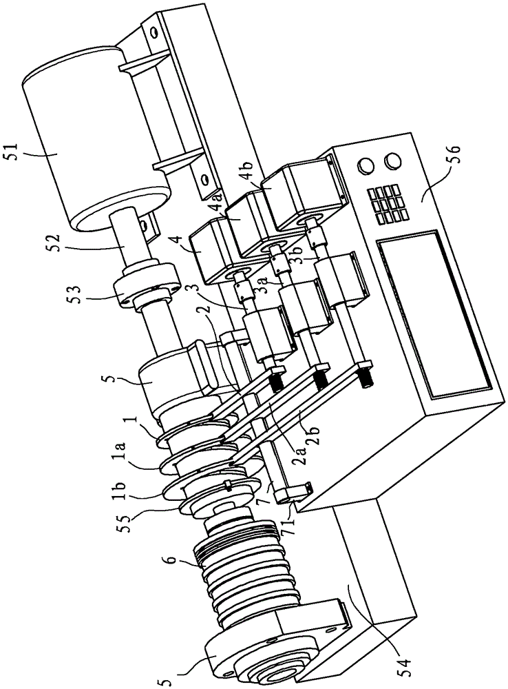
[0038] Example 1, such as Figure 1 to Figure 7 As shown, the high-speed spindle device includes a driving motor 51 and a main shaft 6 connected to an output shaft 52 of the driving motor. The output shaft 52 of the driving motor 51 is adjacent to the main shaft 6 through a coupling 53 . Both ends of the main shaft 6 are respectively provided with support seats 5 , and each support seat 5 is provided with a dynamic balance testing unit capable of sensing whether the main shaft 6 is balanced. The supporting base 5 and the driving motor 51 are disposed on the base plate 54 .
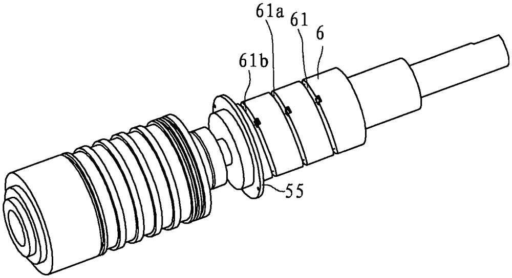
[0039] The main shaft 6 is provided with a balance test connection ring 55 connected with the dynamic balance test unit. The balance test connection ring 55 has a positioning block, which can locate the unbalanced position. The dynamic balance test unit is connected with the computer 56, and the outer wall of the main shaft 6 is sequentially formed with a first chute 61, a second chute 61a and a third chu...
Embodiment 2
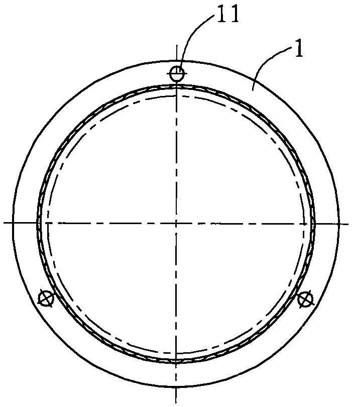
[0053] Example 2, such as Figure 8 ~ Figure 10 As shown, the first chute 61 in this embodiment is a helical right-angle groove, and the inner side of the first adjustment ring 1 is provided with a connecting pin 63 that can slide in the first chute 61. The helical right-angle groove has at least three turns. The second chute 61a is also a helical right-angle groove, and the third chute 61b is also a helical right-angle groove. The helical right-angle grooves are connected into one body, and the three adjusting rings are located in the same helical right-angle groove. For the second adjustment ring 1 a and the third adjustment ring 1 b in this embodiment, refer to the first adjustment ring 1 , and for other structures, refer to Embodiment 1.
Embodiment 3
[0054] Example 3, such as Figure 11 As shown, in this embodiment, the first chute 61 is a closed annular right-angle groove, and the second chute 61a and the third chute 61b are set independently. The second adjustment ring 1a and the third adjustment ring 1b in this embodiment The structures of the second chute 61 a and the third chute 61 b refer to the first adjusting ring 1 and the first chute 61 . Refer to Example 2 for other structures.
PUM
 Abstract
Description
Claims
Application Information
 - R&D
- Intellectual Property
- Life Sciences
- Materials
- Tech Scout
- Unparalleled Data Quality
- Higher Quality Content
- 60% Fewer Hallucinations
Browse by: Latest US Patents, China's latest patents, Technical Efficacy Thesaurus, Application Domain, Technology Topic, Popular Technical Reports.
© 2025 PatSnap. All rights reserved.Legal|Privacy policy|Modern Slavery Act Transparency Statement|Sitemap|About US| Contact US: help@patsnap.com